Introduction
Welcome to the OpenPRoT documentation!
This documentation provides comprehensive information about the OpenPRoT project, including user guides, developer documentation, and API references.
What is OpenPRoT?
OpenPRoT is an open-source, Rust-based project designed to provide a secure and reliable foundation for platform security. It offers a flexible and extensible framework for developing firmware and security-related applications for a variety of platforms.
At its core, OpenPRoT provides a Hardware Abstraction Layer (HAL) that enables platform-agnostic application development. On top of this HAL, it offers a suite of services and protocols for platform security, including device attestation, secure firmware updates, and more.
OpenPRoT is built on Pigweed: pw_kernel is the
microkernel running OpenPRoT targets, pw_log and pw_status are shared
across userspace and firmware code, and the Bazel build plus the ./pw
workflow launcher are Pigweed-managed. See
Pigweed Integration Overview for the full
list of pieces OpenPRoT consumes.
The project is designed with a strong emphasis on modern security protocols and standards, such as:
- SPDM (Security Protocol and Data Model): For secure communication and attestation.
- MCTP (Management Component Transport Protocol): As a transport for management and security protocols.
- PLDM (Platform Level Data Model): For modeling platform components and their interactions.
Project Goals
The primary goals of the OpenPRoT project are to:
- Promote Security: Provide a robust and secure foundation for platform firmware, leveraging modern, industry-standard security protocols.
- Ensure Reliability: Offer a high-quality, well-tested, and reliable codebase for critical platform services.
- Enable Extensibility: Design a modular and extensible architecture that can be easily adapted to different hardware platforms and use cases.
- Foster Collaboration: Build an open and collaborative community around platform security.
Documentation Overview
This documentation is structured to help you understand and use OpenPRoT effectively. Here’s a guide to the different sections:
- Getting Started: A hands-on guide to setting up your development environment and building your first OpenPRoT application.
- Specification: The OpenPRoT specification.
- Repo Structure: A high-level overview of the OpenPRoT repository structure, including its major components and their interactions.
- Usage: Detailed instructions on how to use the OpenPRoT framework and its various services.
- Design: In-depth design documents and specifications for the various components of OpenPRoT.
- Contributing: Guidelines for contributing to the OpenPRoT project.
Repositories
- https://github.com/OpenPRoT/openprot: Main OpenPRoT repository.
- https://github.com/OpenPRoT/mctp-rs: MCTP protocol support for Linux and embedded platforms.
Contact Us
- Email us at openprot-wg@lists.chipsalliance.org
- Join our public mailing list at https://lists.chipsalliance.org/g/openprot-wg
Quick Start
To get started with OpenPRoT, you can build and test the project using the following commands:
./pw presubmit
bazel test //...
For more detailed instructions, please refer to the Getting Started guide.
Governance
The OpenPRoT Technical Charter can be found at here.
Security Policy
Please refer to the Security Policy for more information.
License
Unless otherwise noted, everything in this repository is covered by the Apache License, Version 2.0.
Getting Started
Prerequisites
No additional tools are required - all dependencies are managed by bazel.
Installation
Clone the repository:
git clone https://github.com/OpenPRoT/openprot
cd openprot
Available Tasks
You can run common development tasks using the Pigweed workflow launcher pw or
bazel directly. ./pw is a thin shell wrapper around
bazelisk run //:pw -- "$@", dispatching to workflows defined in
workflows.json.
./pw presubmit- Run presubmit checks: formatting, license checks, C/C++ header checks, andclippy../pw format- Run the code formatters../pw ci- Build and run the host test suite, excluding targets that require real hardware or a verilator sim../pw default- Build everything buildable on a dev host without running tests../pw upstream_pigweed- Full CI plus the Earlgrey verilator tests; used to validate upstream Pigweed bumps.bazel build //docs- Build the mdbook documentation.bazel run //docs:serve- Serve the mdbook onhttp://localhost:8000for local review.
Next Steps
- Read the Usage guide.
- Check out the Architecture documentation.
- Learn about Contributing.
Usage
openprot is built with Bazel and driven through Pigweed's workflow launcher.
The repository is a Bazel module (MODULE.bazel); there is no Cargo
workspace. All everyday tasks go through either ./pw <group> or bazel
directly.
Workflow launcher (./pw)
./pw is a thin wrapper around bazelisk run //:pw -- "$@". It dispatches
to one of the named groups defined in workflows.json:
./pw presubmit         # format check + presubmit_checks analyzer + clippy
./pw format            # apply rustfmt / black / buildifier / clang-format
./pw default           # wildcard build (//... minus //third_party/caliptra/...)
./pw ci                # run CI tests (skips hardware + verilator targets)
./pw upstream_pigweed  # ci tests + Earlgrey verilator tests
./pw presubmit is what you run before every commit. It is also the gate
on CI.
Building and testing with Bazel directly
Use bazelisk (the wrapper accepts every standard bazel flag).
bazel test //...                                                # host tests
bazel build //... --build_tag_filters=-hardware,-disabled       # practical build
bazel build //... --build_tag_filters=-hardware,-disabled,-verilator
bazel test //path/to:target_name                                # single target
The tag filters above are not optional for a wildcard build: //... includes
hardware-only and verilator targets that will fail on a developer machine
without the matching environment. The ci and default workflows already
apply these filters.
Note that //third_party/caliptra/... is intentionally excluded from
wildcard builds (see workflows.json:34, :55, :78). The Caliptra
crate-universe workspaces collide with the host workspace when both are
built unconditionally; build into Caliptra paths explicitly when you need
them.
Clippy
Clippy runs as a rules_rust aspect, not as a separate target:
bazelisk build \
    --aspects=@rules_rust//rust:defs.bzl%rust_clippy_aspect \
    --output_groups=clippy_checks \
    //... -//third_party/caliptra/...
./pw presubmit invokes the same aspect via the clippy build entry.
Documentation
mdbook sources live under docs/. Build with:
bazel build //docs
Tag reference
Targets can carry tags that gate which environment they run in. The common ones used in this tree are:
hardware— requires real silicon; never built locally.verilator— requires a verilator simulator install.disabled— temporarily excluded.manual— never built by//...; only when explicitly named.kernel—pw_kernel-bound system images and supporting targets.
Combine these via --build_tag_filters (build-time) and --test_tag_filters
(test-time). The workflows.json file is the canonical reference for which
filters each workflow applies.
OpenPRoT Specification
Version: v0.5 - Work in Progress
Introduction
The concept of a Platform Root of Trust (PRoT) is central to establishing a secure computing environment. A PRoT is a trusted component within a system that serves as the foundation for all security operations. It is responsible for ensuring that the system boots securely, verifying the integrity of the firmware and software, and performing critical cryptographic functions. By acting as a trust anchor, the PRoT provides a secure starting point from which the rest of the system's security measures can be built. This is particularly important in an era where cyber threats are becoming increasingly sophisticated, targeting the lower layers of the computing stack, such as firmware, to gain persistent access to systems.
OpenPRoT is a project intended to enhance the security and transparency of PRoTs by defining and building an open source firmware stack that can be run on a variety of hardware implementations. Open source firmware offers several benefits that can enhance the effectiveness and trustworthiness of a PRoT. Firstly, open source firmware allows for greater transparency, as the source code is publicly available for review and audit. This transparency helps identify and mitigate vulnerabilities more quickly, as a global community of developers and security experts can scrutinize the code. It also reduces the risk of hidden backdoors or malicious code, which can be a concern with proprietary firmware.
Moreover, an open source firmware stack can foster innovation and collaboration within the industry. By providing a common platform that is accessible to all, developers can contribute improvements, share best practices, and develop new security features that benefit the entire ecosystem. This collaborative approach can lead to more robust and resilient firmware solutions, as it leverages the collective expertise of a diverse community. Additionally, open source firmware can enhance interoperability and reduce vendor lock-in, giving organizations more flexibility in choosing hardware and software components that best meet their security needs.
Incorporating an open source firmware stack into a PRoT not only strengthens the security posture of a system but also aligns with broader industry trends towards openness and collaboration. As organizations increasingly recognize the importance of securing the foundational layers of their computing environments, the combination of a PRoT with open source firmware represents a powerful strategy for building trust and resilience in the face of evolving cyber threats.
Background
Today's Platform Root of Trust (PRoT) solutions are often specifically designed for their target platform, relying on custom interfaces or protocols. This leads to slower time-to-market due to the integration effort required. Customers can become locked into a single solution, making it costly and time-consuming to change suppliers, which in turn introduces supply chain risks.
The Open Platform Root-of-Trust (OpenPRoT) stack is an open and extensible standards-compliant root-of-trust firmware stack for use in root-of-trust elements. The project was initiated to create an OCP specification for a Platform Root of Trust software stack, along with an open-source implementation of that specification. The OpenPRoT stack provides base root-of-trust services in an open architecture that allows hardware vendors to provide both standard and value-added services.
Goals
The vision of the OpenPRoT project is to enable implementation consistency, transparency, openness, reusability, and interoperability. The primary goals of the project are to:
- Create an OCP specification for a Platform Root of Trust (PRoT) firmware stack.
- Create an open-source implementation of the specification.
- Target new and existing PRoT hardware implementations, with a preference for Open Silicon.
- Enable optionality for integrators through stable interfaces while maintaining a high security bar.
- Standardize PRoT hardware interfaces, such as an add-in card connector on the DC-SCM board.
- Promote reusability through collaboration with standards bodies and hardware RoT projects to create robust, modular firmware.
Industry standards and specifications
OpenPRoT is designed to be a standards-based and interoperable Platform Root of Trust (PRoT) solution. This ensures that OpenPRoT can be integrated into a wide range of platforms and that it leverages proven and well-defined security and management protocols.
Distributed Management Task Force (DMTF)
- DSP0274: Security Protocol and Data Model (SPDM) Version 1.3 or later
- DSP0277: Secured Messages using SPDM over MCTP Binding
- DSP0236: Management Component Transport Protocol (MCTP) Base Specification
- DSP0240: Platform Level Data Model (PLDM) Base Specification
- DSP0248: Platform Level Data Model (PLDM) for Platform Monitoring and Control Specification
- DSP0267: Platform Level Data Model (PLDM) for Firmware Update Specification
Trusted Computing Group (TCG)
- DICE Layering Architecture: Device Identity Composition Engine
- DICE Attestation Architecture: Certificate-based attestation
- DICE Protection Environment (DPE): Runtime attestation service
- TCG DICE Concise Evidence Binding for SPDM: Evidence format specification
National Institute of Standards and Technology (NIST)
- NIST SP 800-193: Platform Firmware Resiliency Guidelines
- NIST FIPS 186-5: Digital Signature Standard (DSS)
- NIST SP 800-90A: Recommendation for Random Number Generation
- NIST SP 800-108: Recommendation for Key Derivation Functions
High Level Architecture
The OpenPRoT architecture is designed to be a flexible and extensible platform Root of Trust (PRoT) solution. It is built upon a layered approach that abstracts hardware-specific implementations, providing standardized interfaces for higher-level applications. This architecture promotes reusability, interoperability, and a consistent security posture across different platforms.
Block Diagram
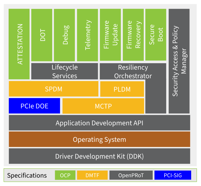
The following block diagram illustrates the high-level architecture of OpenPRoT.
Architectural Layers
The OpenPRoT architecture can be broken down into the following layers:
- Hardware Abstraction Layer (HAL): At the lowest level, the Driver Development Kit (DDK) provides hardware abstractions. This layer is responsible for interfacing with the specific RoT silicon and platform hardware.
- Operating System: Above the DDK sits the operating system, which provides the foundational services for the upper layers.
- Middleware: This layer consists of standardized communication protocols
that enable secure and reliable communication between different components
of the system. Key protocols include:
- MCTP (Management Component Transport Protocol): Provides a transport layer that is compatible with various hardware interfaces.
- SPDM (Security Protocol and Data Model): Used for establishing secure channels and for attestation.
- PLDM (Platform Level Data Model): Provides interfaces for firmware updates and telemetry retrieval.
- Services: This layer provides a minimal set of standardized services
that align with the OpenPRoT specification. These services include:
- Lifecycle Services: Manages the lifecycle state of the device, including secure debug enablement.
- Attestation: Aggregates attestation reports from platform components.
- Firmware Update & Recovery: Orchestrates the secure update and recovery of firmware for platform components.
- Telemetry: Collects and extracts telemetry data.
- Applications: At the highest level are the applications that implement
the core logic of the PRoT. These applications have room for differentiation
while being built upon standardized interfaces. Key applications include:
- Secure Boot: Orchestrates the secure boot process for platform components.
- Policy Manager: Manages the security policies of the platform.
Use Cases
Use cases are divided into two general groups:
- Legacy Admissible Architectures: Where the upstream device, that is, the device attached to the Root of Trust (RoT), boots from SPI NOR Flash EEPROM.
- Modern Admissible Architectures: Where the upstream device supports flash-less boot (i.e., stream boot). Support for modern architectures will be added in a future version of this specification.
Legacy Admissible Architectures
There are three legacy admissible architectures supported by the OpenPRoT implementation:
| Architecture | Common Usages | SPI NOR Flash EEPROM |
|---|---|---|
| Dual-Flash Side-by-side | (Preferred) Most integrations | Two parts, one partition per part (i.e., A + B). |
| Direct-Connect | Add-in devices; board-constrained | One part, double-sized to support A/B updates. |
| TPM | TPM Daughtercard, Onboard TPM | None |
Direct-Connect
In the Direct-Connect architecture, OpenPRoT acts as an SPI interposer between the upstream device and the SPI NOR Flash EEPROM. OpenPRoT examines the opcode of each transaction and decides whether the operation should pass through to the backing SPI Flash or be intercepted and handled by its hardware filtering logic. This policy is controlled by both hardware and firmware. Typically:
- Control operations are handled by the RoT hardware directly.
- Read operations are passed through to the backing SPI Flash.
- Write operations are intercepted by OpenPRoT firmware and may be replayed to the backing SPI flash based on security policy.
OpenPRoT supports atomic A/B updates by diverting read operations to either the lower or upper half of the SPI Flash while hiding the opposing half. This requires the SPI Flash to be double the size needed by the upstream device (e.g., a 512Mbit Flash for a 256Mbit requirement).
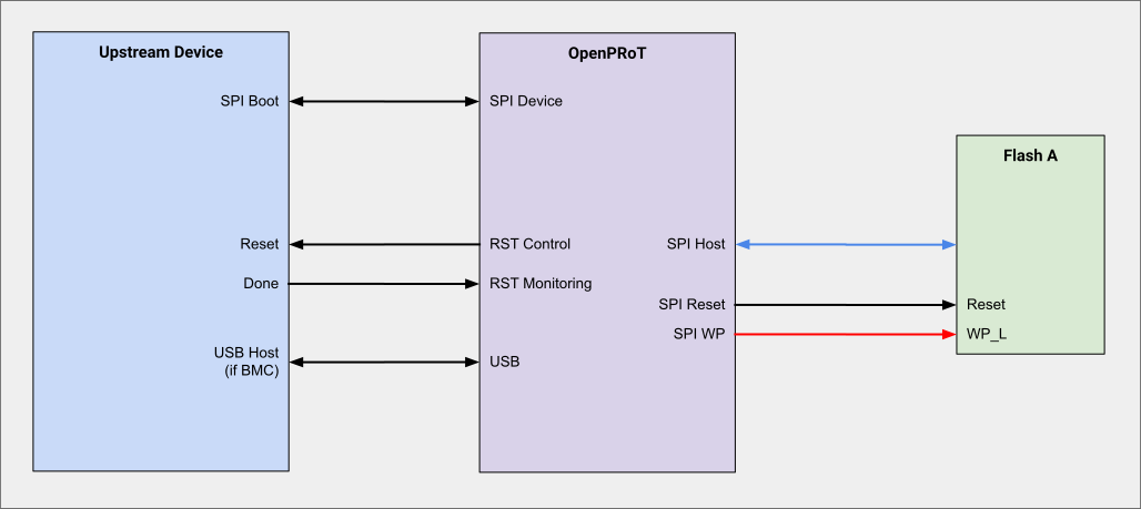
Note: Direct-Connect has a hardware limitation on the maximum supported SPI frequency due to board capacitance, layout, and the PRoT silicon. The integration designer must verify that the expected SPI frequency range is compatible with the upstream device. If this architecture is infeasible, consider the Dual-Flash Side-by-Side architecture instead.
Dual-Flash Side-by-Side
In the Dual-Flash Side-by-Side architecture, the upstream device has direct access to one of two physical SPI NOR Flash EEPROM chips, selected by an OpenPRoT-controlled mux. This arrangement supports atomic A/B updates. OpenPRoT can also directly access each flash chip. The layout should use the smallest possible nets to avoid signal integrity issues from stubs.
Both SPI Flash chips must be the same part. The OpenPRoT firmware coordinates the mux control and its two SPI host interfaces to ensure the nets are not double-driven.
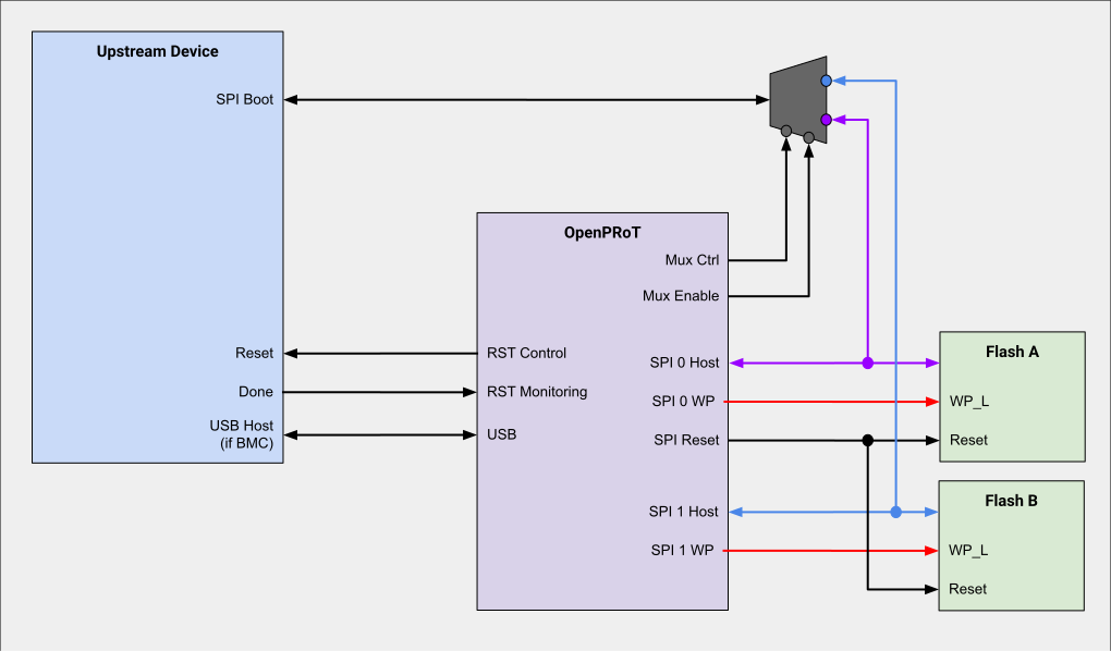
Note: If using quad-SPI, the flash requires a password protection feature, as the Write Protect (WP) pin is not available.
TPM
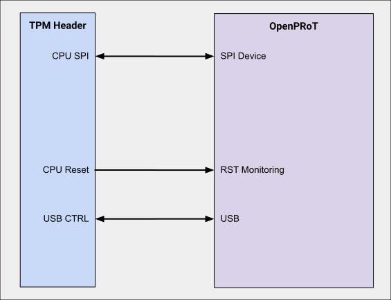
The TPM Admissible Architecture is designed for a direct connection to a standard TPM-SPI interface. In this configuration, OpenPRoT can be soldered onto the main board or placed on a separate daughtercard.
TPM integrations do not require a backing SPI NOR Flash EEPROM and generally only support single-mode SPI. Where possible, these integrations should adhere to a standard TPM connector design.
Threat Model
Assets
- Integrity and authenticity of OpenPRoT firmware
- Integrity and authorization of cryptographic operations
- Integrity of anti-rollback counters
- Integrity and confidentiality of symmetric keys managed by OpenPRoT
- Integrity and confidentiality of private asymmetric keys
- Integrity of boot measurements
- Integrity and authenticity of firmware update payloads
- Integrity and authenticity of OpenPRoT policies
Attacker Profile
The attack profile definition is based on the JIL Application of Attack Potential to Smartcards and Similar Devices Specification version 3.2.1.
- Type of access: physical, remote
- Attacker Proficiency Levels: expert, proficient, laymen
- Knowledge of the TOE: public (open source), critical for signing keys
- Equipment: none, standard, specialized, bespoke
Attacks within Scope
See the JIL specification for examples of attacks.
- Physical attacks
- Perturbation attacks
- Side-channel attacks
- Exploitation of test features
- Attacks on RNG
- Software attacks
- Application isolation
Threat Modeling
To provide a transparent view of the security posture for a given OpenPRoT + hardware implementation, integrators are required to perform a threat modeling analysis. This analysis must evaluate the specific implementation against the assets and attacker profile defined in this document.
The results of this analysis must be documented in table format, with the following columns:
- Threat ID: Unique identifier which can be referenced in documentation and security audits
- Threat Description: Definition of the attack profile and potential attack.
- Target Assets: List of impacted assets
- Mitigation(s): List of countermeasures implemented in hardware and/or software to mitigate the potential attack
- Verification: Results of verification plan used to gain confidence in the mitigation strategy.
Integrators should use the JIL specification as a guideline to identify relevant attacks and must detail the specific mitigation strategies implemented in their design. The table must be populated for the target hardware implementation to allow for a comprehensive security review.
Firmware Resiliency
FW Resiliency Firmware resiliency is a critical concept in modern cybersecurity, particularly as outlined in the NIST SP 800-193 specification. As computing devices become more integral to both personal and organizational operations, the security of their underlying firmware has become paramount. Firmware is often a target for sophisticated cyberattacks because it operates below the operating system, making it a potential vector for persistent threats that can evade traditional security measures. NIST SP 800-193 addresses these concerns by providing a comprehensive framework for enhancing the security and resiliency of platform firmware, ensuring that systems can withstand, detect, and recover from attacks.
The NIST SP 800-193 guidelines focus on three main pillars: protection, detection, and recovery. Protection involves implementing measures to prevent unauthorized modifications to firmware, such as using cryptographic techniques to authenticate updates. Detection is about ensuring that any unauthorized changes to the firmware are quickly identified, which can be achieved through integrity checks and monitoring mechanisms. Recovery is the ability to restore firmware to a known good state after an attack or corruption, ensuring that the system can continue to operate securely. By addressing these areas, the guidelines aim to create a robust defense against firmware-level threats, which are increasingly being exploited by attackers seeking to gain deep access to systems.
In the context of NIST SP 800-193, firmware resiliency is not just about preventing attacks but also about ensuring continuity and trust in the system. The specification recognizes that while it is impossible to eliminate all risks, having a resilient firmware infrastructure can significantly mitigate the impact of potential breaches. This approach is particularly important for critical infrastructure and enterprise environments, where the integrity and availability of systems are crucial. By adopting the principles of NIST SP 800-193, we can enhance our security posture, protect sensitive data, and maintain operational stability in the face of evolving cyber threats.
PRoT Resiliency
TBD
Connected Device Resiliency
TBD
Middleware
OpenPRoT middleware consists of support libraries necessary to implement Root of Trust functionality, telemetry, and firmware management. Support for DMTF protocols such as MCTP, SPDM, and PLDM are provided.
MCTP
MCTP OpenPRoT devices shall support MCTP as the transport for all DMTF protocols.
Versions
The minimum required MCTP version is 1.3.1 (DSP0236.) Support for MCTP 2.0.0 (DSP0256) may be introduced in a future version of this spec.
Required Bindings
Currently only one binding is mandatory in the OpenPRoT specification, though this will change in future versions.
- MCTP over SMBus (DSP0237, 1.2.0)
Recommended Bindings
- MCTP over I3C (DSP0233, 1.0.1)
- MCTP over PCIe-VDM (DSP0238, 1.2.1)
- Only on platforms utilizing PCIe 6 and up.
- MCTP over USB (DSP0283, 1.0.0)
Required Commands
- Set Endpoint ID
- Get Endpoint ID
- Get MCTP Version Support
- Get Message Type Support
- Get Vendor Defined Message Support
- All commands in the range 0xF0 - 0xFF
Optional Commands
- All other commands are optional, but may become required in future revisions.
Development TCP Binding
- OpenPRoT will provide a TCP binding for developmental purposes.
SPDM
SPDM OpenPRoT devices shall use SPDM to conduct all attestation operations both with downstream devices (as a requester) and upstream devices (as a responder.) Devices may choose to act as a requester, a responder, or both. All SPDM version references assume alignment with the most recently released versions of the spec.
OCP Attestation Spec 1.1 Alignment
OpenPRoT implementations of SPDM must align with the OCP Attestation Spec 1.1. All following sections have taken this spec into account. Please refer to that specification for details on specific requirements.
Baseline Version
OpenPRoT sets a baseline version of SPDM 1.2.
Requesters
OpenPRoT devices implementing an SPDM requester will implement support for SPDM 1.2 minimum and may implement SPDM 1.3 and up. The minimum and maximum supported SPDM versions can be changed if support for other versions is not necessary.
Responders
OpenPRoT devices implementing an SPDM responder must implement support for SPDM
1.2 or higher. Responders may only report (via GET_VERSION) a single supported
version of SPDM.
Required Commands
All requesters and responders shall implement the four (4) spec mandatory SPDM commands:
GET_VERSIONGET_CAPABILITIESNEGOTIATE_ALGORITHMSRESPOND_IF_READY
All requesters and responders shall implement the following spec optional commands:
GET_DIGESTSGET_CERTIFICATECHALLENGEGET_MEASUREMENTSGET_CSRSET_CERTIFICATECHUNK_SENDCHUNK_GET
Requesters and responders may implement the following recommended spec optional commands:
- Events
GET_SUPPORTED_EVENT_TYPESSUBSCRIBE_EVENT_TYPESSEND_EVENT
- Encapsulated requests
GET_ENCAPSULATED_REQUESTDELIVER_ENCAPSULATED_RESPONSE
GET_KEY_PAIR_INFOSET_KEY_PAIR_INFOKEY_UPDATEKEY_EXCHANGEFINISHPSK_EXCHANGEPSK_FINISH
All other spec optional commands may be implemented as the integrator sees fit for their use case.
Required Capabilities
CERT_CAP(required forGET_CERTIFICATE)CHAL_CAP(required forCHALLENGE)MEAS_CAP(required forGET_MEASUREMENT)MEAS_FRESH_CAP
Algorithms
The following cryptographic algorithms are accepted for use within OpenPRoT, but may be further constrained by hardware capabilities. At a minimum OpenPRoT hardware must support:
TPM_ALG_ECDSA_ECC_NIST_P384TPM_ALG_SHA3_384
All others are optional and may be used if supported.
- Asymmetric
TPM_ALG_ECDSA_ECC_NIST_P256TPM_ALG_ECDSA_ECC_NIST_P384EdDSA ed25519EdDSA ed448TPM_ALG_SHA_384
- Hash
TPM_ALG_SHA_256TPM_ALG_SHA_384TPM_ALG_SHA_512TPM_ALG_SHA3_256TPM_ALG_SHA3_384TPM_ALG_SHA3_512
- AEAD Cipher
AES-128-GCMAES-256-GCMCHACHA20_POLY1305
Attestation Report Format
Devices will support either RATS EAT (as CWT) or an SPDM evidence manifest TOC per the TCG DICE Concise Evidence for SPDM specification.
Measurement block 0xF0
Devices that do not provide a Measurement Manifest shall locate RATS EAT at SPDM measurement block 0xF0
PLDM
OpenPRoT devices support the Platform Level Data Model (PLDM) as a responder for firmware updates and platform monitoring. This entails responding to messages of Type 0 (Base), Type 2 (Platform Monitoring and Control), and Type 5 (Firmware Update).
PLDM Base Specifications
Type 0 - Base Specification
- Purpose: Base Specification and Initialization
- Version: 1.2.0
- Specification: PLDM Base Specification
All responders must implement the following mandatory PLDM commands:
GetTIDGetPLDMVersionGetPLDMTypesGetPLDMCommands
All responders must also implement the following optional command:
SetTID
Type 2 - Platform Monitoring and Control
- Purpose: Platform Monitoring and Control
- Version: 1.3.0
- Specification: PLDM for Platform Monitoring and Control
OpenPRoT supports PLDM Monitoring and Control by providing a Platform Descriptor Record (PDR) repository to a prospective PLDM manageability access point discovery agent. These PDRs are defined in JSON files and included in OpenPRoT at build time, with no support for dynamic adjustments. The PDRs are limited to security features and will only support PLDM sensors, not effectors.
PLDM Monitoring PDRs
- Terminus Locator PDR
- Numeric Sensor PDR
Type 5 - Firmware Update
- Purpose: Firmware Update
- Version: 1.3.0
- Specification: PLDM for Firmware Update
Required Inventory Commands
QueryDeviceIdentifiersGetFirmwareParameters
Required Update Commands
RequestFirmwareUpdatePassComponentTableUpdateComponentTransferCompleteVerifyCompleteApplyCompleteActivateFirmwareGetStatus
All responders must also implement the following optional commands:
GetPackageDataGetPackageMetaData
Services
The OpenPRoT services layer provides a standardized set of security and management functions that are essential for a Platform Root of Trust (PRoT). Built on top of the middleware and Hardware Abstraction Layer (HAL), this layer offers high-level capabilities that applications can leverage to ensure system integrity, security, and reliability.
The following services are defined in the OpenPRoT specification:
- Firmware Update
- Attestation
- Firmware Recovery (TBD)
- Secure Boot (TBD)
- Policy Management (TBD)
Attestation
1. Introduction
1.1 OpenPRoT Attestation Components
The OpenPRoT firmware stack provides the following attestation capabilities:
SPDM Responder: Enables external relying parties to establish trust in OpenPRoT by:
- Responding to attestation requests over SPDM protocol
- Providing cryptographically signed evidence about platform state
- Supporting both initial trust establishment and periodic re-attestation
- Enabling secure session establishment with authenticated endpoints
SPDM Requester: Enables OpenPRoT to establish trust in other platform components by:
- Requesting attestation evidence from downstream devices
- Verifying device identities and configurations
- Establishing secure sessions with attested devices
- Supporting platform composition attestation
Local Verifier: Enables on-platform verification of attestation evidence by:
- Appraising evidence from platform components without external connectivity
- Supporting air-gapped and latency-sensitive deployments
- Enforcing platform-specific security policies
- Making local trust decisions for platform operations
Note: While OpenPRoT includes a local verifier component, verification can also be performed remotely by external verifiers. The choice between local and remote verification depends on deployment requirements, connectivity constraints, and security policies.
2. Scope and Purpose
2.1 Scope
This specification covers the attestation capabilities provided by the OpenPRoT firmware stack:
In Scope:
- SPDM Responder Implementation: How OpenPRoT responds to external attestation requests
- SPDM Requester Implementation: How OpenPRoT requests attestation from platform devices
- Local Verifier Architecture: On-platform evidence appraisal capabilities
- Evidence Generation: How OpenPRoT firmware collects and reports platform measurements
- Evidence Formats: Standardized structures for conveying attestation claims (OCP RATS EAT, Concise Evidence)
- Protocol Bindings: SPDM protocol integration and message flows
- Device Identity Provisioning: Owner identity provisioning workflows
- Reference Value Integration: How OpenPRoT uses CoRIM for verification
- Plugin Architecture: Extensibility for non-OCP evidence formats
2.2 Out of Scope
This specification does not cover:
Hardware-Specific Details:
- PRoT Hardware Implementations: Specific hardware designs, architectures, and capabilities
- Manufacturing Provisioning: Secret provisioning into hardware (vendor-specific)
- Hardware Root of Trust Mechanisms: Boot ROM implementation, key derivation, measurement collection at hardware level
- Attester Composition: Layered measurement and key derivation (hardware-dependent)
- HAL Trait Implementations: Specific implementations of HAL traits for particular hardware platforms (integrator responsibility)
Note on Hardware Variance: OpenPRoT is a software stack that operates on top of PRoT hardware. The security strength and attestation capabilities of an OpenPRoT-based system depend significantly on the underlying hardware implementation. Hardware vendors must document their specific:
- Root of trust initialization and measurement mechanisms
- Key derivation and protection approaches
- Certificate chain structures
- Cryptographic capabilities and algorithms
- Isolation and protection boundaries
Other Out of Scope Items:
- OpenPRoT Firmware Implementation Details: Internal firmware architecture (covered in OpenPRoT project documentation)
- Application-level Attestation Policies: Use-case specific verification policies
- Cryptographic Algorithm Specifications: Defers to NIST and industry standards
- Remote Verifier Implementation: External verifier systems (though evidence format is specified)
- Reference Value Provider Services: CoRIM generation and distribution infrastructure
- Transport Layer Details: Physical/link layer protocols (I2C, I3C, MCTP, etc.)
3. Normative References
The following standards are normatively referenced in this specification:
3.1 IETF Specifications
- RFC 9334: Remote ATtestation procedureS (RATS) Architecture
- RFC 9711: Entity Attestation Token (EAT)
- CoRIM: Concise Reference Integrity Manifest (IETF Draft)
- RFC 8949: Concise Binary Object Representation (CBOR)
- RFC 9052: CBOR Object Signing and Encryption (COSE)
- RFC 5280: Internet X.509 Public Key Infrastructure Certificate and CRL Profile
3.2 TCG Specifications
- DICE Layering Architecture: Device Identity Composition Engine
- DICE Attestation Architecture: Certificate-based attestation
- DICE Protection Environment (DPE): Runtime attestation service
- TCG DICE Concise Evidence Binding for SPDM: Evidence format specification
3.3 DMTF Specifications
- DSP0274: Security Protocol and Data Model (SPDM) Version 1.3 or later
- DSP0277: Secured Messages using SPDM over MCTP Binding
- DSP0236: Management Component Transport Protocol (MCTP) Base Specification
3.4 Other Standards
- NIST FIPS 186-5: Digital Signature Standard (DSS)
- NIST SP 800-90A: Recommendation for Random Number Generation
- NIST SP 800-108: Recommendation for Key Derivation Functions
4. Terminology and Definitions
4.1 Attestation Roles
Following IETF RATS RFC 9334, the OpenPRoT attestation architecture defines the following roles:
Attester: An entity (OpenPRoT firmware and associated platform components) that produces attestation evidence about its state and configuration.
Relying Party: An entity that depends on the validity of attestation evidence to make operational decisions. In OpenPRoT deployments, this is typically:
- External platform owner or management system (for initial trust establishment)
- Platform management controller (for periodic verification)
- Cloud service provider infrastructure (for fleet management)
Verifier: An entity that appraises attestation evidence against reference values and policies to produce attestation results. OpenPRoT supports:
- Local Verifier: Running within OpenPRoT firmware for on-platform verification
- Remote Verifier: External system performing verification (implementation not specified here)
Endorser: An entity that vouches for the authenticity and properties of attestation components. For OpenPRoT:
PRoT Hardware: The underlying hardware platform that provides the root of trust capabilities (secure boot, cryptographic acceleration, isolated execution, OTP storage).
SPDM Responder Role: OpenPRoT acting as an SPDM responder to provide attestation evidence to external requesters.
SPDM Requester Role: OpenPRoT acting as an SPDM requester to obtain attestation evidence from platform devices.
Local Verifier: The verification component within OpenPRoT that appraises evidence from platform devices without requiring external connectivity.
Platform Composition: The complete set of attested components including OpenPRoT and downstream devices.
4.3 Key Attestation Terms
Root of Trust (RoT): The foundational hardware and immutable firmware that serves as the trust anchor for the platform. In OpenPRoT context, this is the PRoT hardware's boot ROM.
Compound Device Identifier (CDI): A cryptographic secret derived from measurements and used as the basis for key derivation in DICE.
Target Environment: A uniquely identifiable component or configuration that is measured and attested. In OpenPRoT:
- OpenPRoT firmware components (bootloader, runtime firmware)
- Hardware configurations (fuse settings, security configurations)
- Platform devices (when acting as SPDM requester)
TCB (Trusted Computing Base): The set of components that must be trusted for the security properties of a system to hold.
Evidence: Authenticated claims about platform state produced by the Attester. OpenPRoT generates evidence in multiple formats:
- DICE certificates with TCBInfo extensions
- TCG Concise Evidence
- RATS Entity Attestation Token (EAT)
Reference Values: Known-good measurements provided by the Reference Value Provider for comparison during verification. Typically distributed as CoRIM (Concise Reference Integrity Manifest).
Endorsement: Authenticated statements about device properties or certifications.
Appraisal Policy: Rules used by the Verifier to evaluate evidence against reference values.
Freshness: Property ensuring that evidence represents current platform state, typically achieved through nonces or timestamps.
4.4 DICE/DPE Terms
UDS (Unique Device Secret): A hardware-unique secret provisioned during manufacturing, stored in OTP/fuses, used as the root secret for DICE key derivation.
IDevID (Initial Device Identity): The manufacturer-provisioned device identity derived from UDS.
LDevID (Local Device Identity): An operator-provisioned device identity that can be used in place of IDevID.
Alias Key: A DICE-derived key that represents a specific layer in the boot chain.
DPE (DICE Protection Environment): A service that extends DICE principles to runtime, allowing dynamic context creation and key derivation.
DPE Context: A chain of measurements representing a specific execution path through the system.
DPE Handle: An identifier for a specific DPE context, used to extend measurements or derive keys.
4.5 SPDM Terms
SPDM Session: An authenticated and optionally encrypted communication channel between SPDM requester and responder.
Measurement Block: A collection of measurements representing a specific component or configuration.
Slot: An SPDM certificate chain storage location (Slot 0-7).
GET_MEASUREMENTS: SPDM command to retrieve attestation measurements.
GET_CERTIFICATE: SPDM command to retrieve certificate chains.
CHALLENGE: SPDM command to request signed evidence with freshness.
5. Attestation Architecture Overview
5.1 RATS Architecture Mapping
OpenPRoT implements the IETF RATS architecture with specific role assignments:
High-Level Flow:
- Relying Party (Platform Owner, CSP, Management System) needs to establish trust in the platform
- Relying Party requests attestation evidence from OpenPRoT via SPDM
- OpenPRoT (Attester) generates evidence containing measurements and claims
- Verifier (Remote or Local) receives evidence and appraises it
- Verifier retrieves reference values and endorsements from Reference Value Provider
- Verifier applies appraisal policy and generates attestation result
- Attestation result is conveyed to Relying Party
- Relying Party makes trust decision based on attestation result
Components:
- Attester: OpenPRoT Firmware Stack + PRoT Hardware
- Verifier: Remote verifier system OR OpenPRoT Local Verifier (for device attestation)
- Relying Party: External management system OR OpenPRoT (when verifying devices)
- Reference Value Provider: OpenPRoT project, hardware vendors, platform integrators
- Endorser: Hardware vendors, OpenPRoT project, platform integrators
5.2 Evidence Format Strategy
OpenPRoT adopts a standardized approach to evidence generation and verification:
5.2.1 OpenPRoT Evidence Generation (SPDM Responder)
When acting as an SPDM Responder, OpenPRoT produces attestation evidence in the following formats:
Primary Evidence Format: RATS EAT with OCP Profile
OpenPRoT generates Entity Attestation Tokens (EAT) following the OCP RATS EAT Attestation Profile. This format provides:
- Standardized container for attestation claims
- CBOR-encoded for efficiency
- COSE-signed for authenticity
- Nonce-based freshness
- TCG Concise Evidence embedded in measurements claim
EAT Structure:
The OpenPRoT EAT follows the OCP RATS EAT Attestation Profile specification. For complete details on the EAT structure, claims, and encoding, see:
https://opencomputeproject.github.io/Security/ietf-eat-profile/HEAD/
Supporting Evidence Formats:
- DICE Certificates with TCBInfo: Certificate chain establishing device identity and boot measurements
- TCG Concise Evidence: Standalone format containing reference-triples for measurements
- SPDM Measurement Blocks: Native SPDM measurement format for basic compatibility
5.2.2 OpenPRoT Evidence Verification (Local Verifier)
When acting as a Local Verifier, OpenPRoT supports multiple evidence formats:
Native Support: OCP RATS EAT Profile
The OpenPRoT Local Verifier natively supports appraisal of evidence in OCP RATS EAT Attestation Profile format. This enables:
- Standardized verification logic for OCP-compliant devices
- Consistent appraisal policy across vendors
- Interoperability with OCP ecosystem devices
- Direct comparison against CoRIM reference values
Verification Process for OCP EAT:
- Validate EAT signature using device certificate chain
- Verify nonce freshness
- Extract Concise Evidence from measurements claim
- Retrieve CoRIM reference values using corim-locator
- Compare evidence reference-triples against CoRIM reference-triples
- Apply appraisal policy
- Generate attestation result
Extended Support: Evidence Format Plugins
To accommodate diverse platform ecosystems, OpenPRoT includes an extensibility mechanism for non-OCP-compliant evidence formats:
Plugin Architecture:
- Evidence Parser Plugins: Parse vendor-specific evidence formats
- Claim Extractor Plugins: Extract measurements and claims from proprietary formats
- Policy Adapter Plugins: Map vendor-specific claims to OpenPRoT appraisal policies
Use Cases for Plugins:
- Legacy devices with proprietary attestation formats
- Vendor-specific evidence structures not yet migrated to OCP profile
- Specialized evidence formats for specific device classes
- Transitional support during ecosystem migration to OCP standards
Plugin Interface Requirements:
Plugins must implement the following interfaces:
- parse_evidence(): Convert vendor format to internal representation
- extract_claims(): Extract target environments and measurements
- validate_signature(): Verify evidence authenticity
- get_reference_values(): Retrieve or map to reference values
- apply_policy(): Execute appraisal logic
Plugin Integration:
Platform integrators can add custom plugins to OpenPRoT's local verifier to support their specific device ecosystem while maintaining the core OCP-compliant verification path for standard devices.
5.3 OpenPRoT Dual Role Architecture
OpenPRoT operates in two distinct attestation roles depending on the interaction:
5.3.1 OpenPRoT as Attester (SPDM Responder)
When external relying parties need to establish trust in OpenPRoT:
Flow:
- External Relying Party (SPDM Requester) initiates SPDM session
- SPDM version negotiation and capability exchange
- Algorithm negotiation
- Certificate chain retrieval (GET_CERTIFICATE)
- Measurement request (GET_MEASUREMENTS) with nonce
- OpenPRoT (SPDM Responder) generates EAT with OCP profile
- OpenPRoT returns signed EAT containing Concise Evidence
- Verifier (remote) appraises evidence against reference values
- Attestation result returned to Relying Party
Evidence Provided by OpenPRoT:
- Certificate chain (structure determined by underlying PRoT hardware implementation)
- RATS EAT with OCP Profile containing:
- TCG Concise Evidence with reference-triples
- Freshness nonce
- CoRIM locator URI
- COSE signature using attestation key provided by underlying hardware
Note on Hardware Dependencies:
The certificate chain structure and attestation key derivation mechanisms are determined by the underlying PRoT hardware implementation and are outside the scope of OpenPRoT firmware. OpenPRoT leverages the attestation capabilities provided by the hardware platform. Hardware vendors should document their specific:
- Certificate chain structure and hierarchy
- Key derivation mechanisms
- Supported cryptographic algorithms
- Identity provisioning approach
Use Cases:
- Initial platform deployment and trust establishment
- Periodic re-attestation for fleet management
- Pre-workload-deployment verification
- Compliance auditing
5.3.2 OpenPRoT as Verifier (SPDM Requester + Local Verifier)
When OpenPRoT needs to establish trust in platform devices:
Flow:
- OpenPRoT (SPDM Requester) initiates SPDM session with platform device
- SPDM version negotiation and capability exchange
- Algorithm negotiation
- Certificate chain retrieval from device (GET_CERTIFICATE)
- Measurement request (GET_MEASUREMENTS) with nonce
- Platform Device (SPDM Responder) returns evidence
- OpenPRoT Local Verifier receives evidence
- If OCP EAT format: Native verification path
- If non-OCP format: Plugin-based verification path
- Local Verifier appraises evidence against reference values
- Local trust decision made by OpenPRoT
- Result used for platform composition decisions
Standard Measurement Transcript:
OpenPRoT follows the DMTF SPDM Single-request Measurement Transcript for evidence collection from devices. This standardized approach ensures consistent evidence structure across different device types and vendors.
Evidence Received by OpenPRoT:
- Device certificate chain (structure varies by device implementation)
- Device evidence (OCP EAT preferred, plugin-supported formats allowed)
- Device measurements and claims in Standard Measurement Report format
Verification Paths:
- OCP-Compliant Devices: Direct verification using native OCP EAT verifier
- Non-OCP Devices: Plugin-based parsing and verification
- Hybrid Platforms: Mix of OCP and non-OCP devices verified appropriately
Use Cases:
- Verifying network cards, storage controllers, accelerators, soc
- Establishing trust in platform composition
- Air-gapped deployments without external verifier access
- Real-time device trust decisions
5.4 Attestation Flow
The basic attestation flow follows these steps:
Phase 1: Measurement Collection (Boot Time)
- PRoT Hardware Boot ROM (immutable) starts execution
- Boot ROM measures OpenPRoT bootloader (First Mutable Code)
- Hardware-specific key derivation and certificate generation occurs
- Control transfers to OpenPRoT bootloader
- Bootloader measures OpenPRoT runtime firmware
- Hardware-specific measurement chain continues
- Control transfers to OpenPRoT runtime firmware
- Runtime firmware initializes attestation services
- Runtime firmware measures platform components (optional)
Note: The specific measurement and key derivation mechanisms in steps 3 and 6 are hardware-dependent and outside the scope of OpenPRoT firmware.
Phase 2: Evidence Generation (On Request)
- External requester initiates SPDM session with OpenPRoT
- OpenPRoT SPDM Responder receives attestation request (GET_MEASUREMENTS)
- OpenPRoT collects current measurements from platform state
- OpenPRoT formats measurements as TCG Concise Evidence (reference-triples)
- OpenPRoT constructs RATS EAT with OCP Profile:
- Sets issuer to OpenPRoT identifier
- Includes requester-provided nonce
- Embeds Concise Evidence in measurements claim
- Adds CoRIM locator URI
- OpenPRoT signs EAT using hardware-provided attestation key (COSE signature)
- OpenPRoT returns EAT and certificate chain to requester
Phase 3: Evidence Conveyance
- SPDM Responder transmits evidence via SPDM protocol
- Evidence includes:
- Certificate chain (for signature verification)
- Signed EAT (containing measurements)
- Optional: Additional endorsements
- Transport layer delivers evidence to verifier
Phase 4: Reference Value Retrieval
- Verifier extracts CoRIM locator from EAT
- Verifier retrieves reference values CoRIM from repository
- Verifier retrieves endorsements (device identity, certifications)
- Verifier validates CoRIM signatures
- Verifier loads appraisal policy
Phase 5: Appraisal
- Verifier validates EAT signature using certificate chain
- Verifier checks certificate chain to trusted root
- Verifier verifies nonce freshness
- Verifier extracts Concise Evidence from EAT measurements claim
- Verifier parses reference-triples from Concise Evidence
- For each target environment in evidence:
- Compare against CoRIM reference values
- Check measurements match expected values
- Verify SVN meets minimum requirements
- Apply policy rules
- Verifier generates attestation result
Phase 6: Trust Decision
- Attestation result conveyed to Relying Party
- Relying Party evaluates result against requirements
- Relying Party makes operational decision:
- Accept platform for use
- Reject platform
- Request additional evidence
- Apply restricted usage policy
5.5 Trust Model
OpenPRoT's attestation architecture relies on the following trust assumptions:
5.5.1 Hardware Trust Anchor
Trusted Components:
- PRoT Hardware Boot ROM (immutable code)
- Hardware cryptographic accelerators
- OTP/Fuse storage for device secrets
- Hardware isolation mechanisms
Assumptions:
- Boot ROM is free from vulnerabilities
- Hardware random number generation is cryptographically secure
- Secrets in OTP/fuses cannot be extracted
- Hardware isolation prevents unauthorized access to secrets
Hardware-Specific Trust:
The specific trust properties and security guarantees are determined by the underlying PRoT hardware implementation. Hardware vendors must document:
- Root of trust initialization process
- Secret storage mechanisms
- Key derivation approach
- Isolation boundaries
- Cryptographic capabilities
5.5.2 Firmware Trust Chain
Trust Establishment:
- Boot ROM measures and authenticates OpenPRoT bootloader
- Bootloader measures and authenticates OpenPRoT runtime
- Each layer's measurements are recorded
- Compromise of any layer results in detectable measurement changes
Properties:
- Measurements cannot be forged without detection
- Certificate chain provides cryptographic proof of boot integrity
- Hardware-specific key binding ensures authenticity
OpenPRoT Scope:
OpenPRoT firmware operates within the trust chain established by the underlying hardware. The firmware:
- Collects and reports measurements
- Generates evidence in standardized formats
- Implements SPDM responder and requester roles
- Provides local verification capabilities
The underlying measurement and key derivation mechanisms are hardware-dependent.
5.6 Threats and Migitations
Cryptographic Assumptions:
- Digital signatures cannot be forged without private key
- Hash collisions are computationally infeasible
- Key derivation functions provide one-way security
- COSE signature scheme provides authenticity and integrity
5.6.1 False Reference Values
Threat: Attacker provides false reference values to verifier
Mitigation:
- CoRIM signed by trusted authority
- Verifier validates CoRIM signature before use
- Secure distribution channels for reference values
- Verifier configured with trusted root certificates
5.6.2 Man-in-the-Middle Attacks
Threat: Attacker intercepts and modifies attestation messages
Mitigation:
- SPDM secure sessions provide encryption and authentication
- Evidence signed by device prevents modification
- Certificate-based mutual authentication
- Integrity protection on all messages
5.6.3 Plugin Exploitation
N/A. OpenPRoT does not support plugins.
5.7 Device Identity Provisioning
OpenPRoT supports flexible device identity provisioning to accommodate different deployment models and ownership scenarios.
5.7.1 Identity Types
Manufacturer-Provisioned Identity:
- Provisioned by hardware manufacturer during production
- Rooted in hardware-unique secrets
- Provides vendor attestation anchor
- Permanent identity tied to hardware
Owner-Provisioned Identity:
- Provisioned by platform owner during deployment
- Enables owner-controlled attestation anchor
- Supports organizational PKI integration
- Can be updated by authorized owner
5.7.2 Owner Identity Provisioning with OpenPRoT
OpenPRoT implements the OCP Device Identity Provisioning specification to enable platform owners to provision owner-controlled identities to devices under their control. OpenPRoT acts as the intermediary between the owner and the device, facilitating secure identity provisioning.
Provisioning Process:
The owner identity provisioning follows the standardized flow defined in the OCP specification:
-
Owner Initiates Provisioning: Owner uses OpenPRoT to begin owner identity provisioning process
-
CSR Collection: OpenPRoT collects Certificate Signing Request (CSR) from the target device
- Device generates identity key pair internally
- Device creates CSR containing public key
- OpenPRoT retrieves CSR from device
-
Trust Establishment: OpenPRoT establishes trust in the device's identity key
- Verifies device's manufacturer-provisioned identity certificate chain
- Validates that CSR is signed by device
- Confirms key is hardware-protected
- Provides attestation evidence to owner
-
Endorsement Generation: Owner generates identity endorsement
- Owner reviews device attestation evidence
- Owner verifies device trustworthiness
- Owner signs CSR with owner CA
- Owner creates identity certificate
-
Endorsement Provisioning: OpenPRoT provisions the endorsement to the device
- OpenPRoT receives signed identity certificate from owner
- OpenPRoT provisions identity certificate to device
- Device validates and stores identity certificate
-
Verification: OpenPRoT verifies successful provisioning
- Requests device to use owner-provisioned identity for attestation
- Validates identity certificate chain
- Confirms device can sign with identity key
OpenPRoT's Role:
- CSR Broker: Retrieves CSRs from devices
- Trust Validator: Verifies device identity and key protection before owner endorsement
- Provisioning Agent: Delivers owner-signed certificates to devices
- Verification Service: Confirms successful identity provisioning
Benefits:
- Owner Control: Platform owners control their attestation trust anchor
- PKI Integration: Enables integration with organizational PKI infrastructure
- Privacy: Owner-provisioned identity can provide privacy from manufacturer tracking
- Flexibility: Supports diverse deployment and ownership models
- Automated Workflow: OpenPRoT automates the provisioning process
Specification Reference:
For complete details on the device identity provisioning process, see:
https://opencomputeproject.github.io/Security/device-identity-provisioning/HEAD/
6. Claims and Target Environments
TODO: Define OpenPRoT-specific claims and target environment structures
7. Evidence Formats
TODO: Detail evidence format specifications for OpenPRoT
8. Reference Values and Endorsements
TODO: Describe reference value and endorsement mechanisms
9. SPDM Protocol Integration
TODO: Specify SPDM protocol bindings and requirements
10. Local Verifier
TODO: Define local verifier architecture and capabilities
11. Attestation Use Cases
TODO: Document common attestation scenarios and workflows
12. Security Considerations
TODO: Additional security considerations beyond threat model
13. Implementation Guidelines
TODO: Guidance for implementers of OpenPRoT attestation
Firmware Update
Status: Draft
Overview
This section details the OpenPRoT firmware update mechanism, incorporating the DMTF standards for PLDM and SPDM, while emphasizing the security and resilience principles of the project.
Goals
- To provide a secure and reliable method for updating OpenPRoT firmware.
- To ensure that firmware updates are authenticated and authorized.
- To provide a recovery mechanism in the event of a failed update.
- To align with industry standards for firmware updates (PLDM, SPDM).
Use Cases
- Updating the OpenPRoT firmware itself.
- Updating the firmware of downstream devices managed by OpenPRoT.
- Applying critical security updates and bug fixes.
- Updating firmware to enable new features.
PLDM for Firmware Update
OpenPRoT devices will support PLDM Type 5 version 1.3.0 for Firmware Updates. This will be the primary mechanism for transferring firmware images and metadata to the device. PLDM provides a standardized method for managing firmware updates and is particularly well-suited for out-of-band management scenarios.
PLDM Firmware Update Package
The firmware update package is essential for conveying the information required for the PLDM Firmware Update commands.
Package Header
The package will contain a header that describes the contents of the firmware update package, including:
- Overall packaging version and date.
- Device identifier records to specify the target OpenPRoT devices.
- Downstream device identifier records to describe target downstream devices.
- Component image information, including classification, offset, size, and version.
- A checksum for integrity verification.
- Package Payload: Contains the actual firmware component images to be updated
Package Header Information
| Field | Size (bytes) | Definition |
|---|---|---|
| PackageHeaderIdentifier | 16 | Set to 0x7B291C996DB64208801B0202E6463C78 (v1.3.0 UUID) (big endian) |
| PackageHeaderFormatRevision | 1 | Set to 0x04 (v1.3.0 header format revision) |
| PackageHeaderSize | 2 | The total byte count of this header structure, including fields within the Package Header Information, Firmware Device Identification Area, Downstream Device Identification Area, Component Image Information Area, and Checksum sections. |
| PackageReleaseDateTime | 13 | The date and time when this package was released in timestamp104 formatting. Refer to the PLDM Base Specification for field format definition. |
| ComponentBitmapBitLength | 2 | Number of bits used to represent the bitmap in the ApplicableComponents field for a matching device. This value is a multiple of 8 and is large enough to contain a bit for each component in the package. |
| PackageVersionStringType | 1 | The type of string used in the PackageVersionString field. Refer to DMTF Firmware Update Specification v.1.3.0 Table 33 for values. |
| PackageVersionStringLength | 1 | Length, in bytes, of the PackageVersionString field. |
| PackageVersionString | Variable | Package version information, up to 255 bytes. Contains a variable type string describing the version of this firmware update package. |
| DeviceIDRecordCount | uint8 | The count of firmware device ID records that are defined within this package. |
| FirmwareDeviceIDRecords | Variable | Contains a record, a set of descriptors, and optional package data for each firmware device within the count provided from the DeviceIDRecordCount field. |
Firmware Device ID Descriptor
| Field | Size (bytes) | Definition |
|---|---|---|
| RecordLength | 2 | The total length in bytes for this record. The length includes the RecordLength, DescriptorCount, DeviceUpdateOptionFlags, ComponentImageSetVersionStringType, ComponentSetVersionStringLength, FirmwareDevicePackageDataLength, ApplicableComponents, ComponentImageSetVersionString, and RecordDescriptors, and FirmwareDevicePackageData fields. |
| DescriptorCount | 1 | The number of descriptors included within the RecordDescriptors field for this record. |
| DeviceUpdateOptionFlags | 4 | 32-bit field where each bit represents an update option. bit 0 is set to 1 (Continue component updates after failure). |
| ComponentImageSetVersionStringType | 1 | The type of string used in the ComponentImageSetVersionString field. Refer to DMTF Firmware Update Specification v.1.3.0 Table 33 for values. |
| ComponentImageSetVersionStringLength | 1 | Length, in bytes, of the ComponentImageSetVersionString. |
| FirmwareDevicePackageDataLength | 2 | Length in bytes of the FirmwareDevicePackageData field. If no data is provided, set to 0x0000. |
| ReferenceManifestLength | 4 | Length in bytes of the ReferenceManifestData field. If no data is provided, set to 0x00000000. |
| ApplicableComponents | Variable | Bitmap indicating which firmware components apply to devices matching this Device Identifier record. A set bit indicates the Nth component in the payload is applicable to this device. bit 0: OpenPRoT RT Image bit 1: Downstream SoC Manifest bit 2 : Downstream SoC Firmware bit 3:: Downstream EEPROM |
| ComponentImageSetVersionString | Variable | Component Image Set version information, up to 255 bytes. Describes the version of component images applicable to the firmware device indicated in this record. |
| RecordDescriptors | Variable | These descriptors are defined by the vendor. Refer to DMTF Firmware Update Specification v.1.3.0 Table 7 for details of these fields and the values that can be selected. |
| FirmwareDevicePackageData | Variable | Optional data provided within the firmware update package for the FD during the update process. If FirmwareDevicePackageDataLength is 0x0000, this field contains no data. |
| ReferenceManifestData | Variable | Optional data field containing a Reference Manifest for the firmware update. If present, it describes the firmware update provided by this package. If ReferenceManifestLength is 0x00000000, this field contains no data. |
Downstream Device ID Descriptor
| Field | Size | Definition |
|---|---|---|
| DownstreamDeviceIDRecordCount | 1 | 0 |
Component Image Information
| Field | Size | Definition |
|---|---|---|
| ComponentClassification | 2 | 0x000A: Downstream EEPROM, Downstream SoC Firmware, and OpenPRoT RT Image (Firmware), 0x0001: Downstream SoC Manifest (Other) |
| ComponentIdentifier | 2 | Unique value selected by the FD vendor to distinguish between component images. 0x0001: OpenPRoT RT Image, 0x0002: Downstream SoC Manifest, 0x0003: 0x0003: Downstream EEPROM 0x1000-0xFFFF - Reserved for other vendor-defined SoC images |
| ComponentComparisonStamp | 4 | Value used as a comparison in determining if a firmware component is down-level or up-level. When ComponentOptions bit 1 is set, this field should use a comparison stamp format (e.g., MajorMinorRevisionPatch). If not set, use 0xFFFFFFFF. |
| ComponentOptions | 2 | Refer to ComponentOptions definition in DMTF Firmware Update Specification v.1.3.0 |
| RequestedComponentActivationMethod | 2 | Refer to RequestedComponentActivationMethoddefinition inDMTF Firmware Update Specification v.1.3.0 |
| ComponentLocationOffset | 4 | Offset in bytes from byte 0 of the package header to where the component image begins. |
| ComponentSize | 4 | Size in bytes of the Component image. |
| ComponentVersionStringType | 1 | Type of string used in the ComponentVersionString field. Refer toDMTF Firmware Update Specification v.1.3.0 Table 33 for values. |
| ComponentVersionStringLength | 1 | Length, in bytes, of the ComponentVersionString. |
| ComponentVersionString | Variable | Component version information, up to 255 bytes. Contains a variable type string describing the component version. |
| ComponentOpaqueDataLength | 4 | Length in bytes of the ComponentOpaqueData field. If no data is provided, set to 0x00000000. |
| ComponentOpaqueData | Variable | Optional data transferred to the FD/FDP during the firmware update |
Component Identifiers
| Component Image | Name | Description |
|---|---|---|
| 0x0 | OpenPRoT RT Image | OpenPRoT manifest and firmware images (e.g. BL0, RT firmware). |
| 0x1 | Downstream SoC Manifest | SoC manifest covering firmware images. Used to stage verification of the firmware payload. |
| 0x2 | Downstream SoC Firmware | SoC firmware payload. |
| 0x3 | Downstream EEPROM | Bulk update of downstream EEPROM |
| >= 0x1000 | Vendor defined components |
PLDM Firmware Update Process
The update process will involve the following steps:
- RequestUpdate: The Update Agent (UA) initiates the firmware update by
sending the
RequestUpdatecommand to the OpenPRoT device. We refer to OpenPRoT as the Firmware Device (FD). - GetPackageData: If there is optional package data for the Firmware Device (FD), the UA will transfer it to the FD prior to transferring component images.
- GetDeviceMetaData: The UA may also optionally retrieve FD metadata that will be saved and restored after all components are updated.
- PassComponentTable: The UA will send the
PassComponentTablecommand with information about the component images to be updated. This includes the identifier, component comparison stamp, classification, and version information for each component image. - UpdateComponent: The UA will send the
UpdateComponentcommand for each component, which includes: component classification, component version, component size, and update options. The UA will subsequently transfer component images using theRequestFirmwareDatacommand.. - TransferComplete: After successfully transferring component data, the FD
will send a
TransferCompletecommand. - VerifyComplete: Once a component transfer is complete the FD will perform a verification of the image.
- ApplyComplete: The FD will use the
ApplyCompletecommand to signal that the component image has been successfully applied. - ActivateFirmware: After all components are transferred, the UA sends the
ActivateFirmwarecommand. If self-contained activation is supported, the FD should immediately enable the new component images. Otherwise, the component enters a "pending activation" state which will require a reset to complete the activation. - GetStatus: The UA will periodically use the
GetStatuscommand to detect when the activation process has completed.
For downstream device updates, the UA will use RequestDownstreamDeviceUpdate
to initiate the update sequence on the FDP. The rest of the process is similar,
with the FDP acting as a proxy for the downstream device.
PLDM Firmware Update Error Handling and Recovery
- The PLDM specification defines a set of completion codes for error conditions.
- OpenPRoT will adhere to the timing specifications defined in the PLDM specification (DSP0240 and DSP0267) for command timeouts and retries.
- The
CancelUpdateComponentcommand is available to cancel the update of a component image, and theCancelUpdatecommand can be used to exit from update mode. The UA should attempt to complete the update and avoid cancelling if possible. - OpenPRoT devices will implement a dual-bank approach for firmware
components. This will allow for a fallback to a known-good firmware image in
case of a failed update. If a power loss occurs prior to the
ActivateFirmwarecommand, the FD will continue to use the currently active image, and the UA can restart the firmware update process.
Device Abstraction
Status: Draft
The OpenPRoT Driver Development Kit (Device Development Kit) provides a set of generic Rust traits and types for interacting with I/O peripherals and cryptographic algorithm accelerators encountered in the class of devices that perform Root of Trust (RoT) functions.
The DDK isolates the OpenPRoT developer from the underlying embedded processor and operating system.
Scope
This section provides a non-exhaustive list of peripherals that fall within the scope of the Device Driver Kit (DDK).
I/O Peripherals
| Device | Description |
|---|---|
| SMBus/I2C Monitor/Filter | |
| Delay | Delay execution for specified durations in microseconds or milliseconds. |
Cryptographic Functions
| Cryptographic Algorithm | Description |
|---|---|
| AES | Symmetric encryption and decryption |
| ECC | ECDSA signature and verification |
| digest | Cryptographic hash functions |
| RSA | RSA signature and verification |
We will refer to the collection of I/O peripherals and cryptographic algorithm accelerators as peripherals from now on.
Design Goals
Platform Agnostic
The goal of the DDK is to provide a consistent and flexible interface for applications to invoke peripheral functionality, regardless of whether the interaction with the underlying peripheral driver is through system calls to a kernel mode device driver, inter-task communication or direct access to memory-mapped peripheral registers.
Execution Model Agnostic
The DDK should be agnostic of the execution model and provide flexibility for its users.
The collection of traits in the DDK is to be segregated in different crates according to the APIs it exposes. i.e. synchronous, asynchronous, and non-blocking APIs.
These crates ensure that DDK can cater to various execution models, making it versatile for different application requirements.
- Synchronous APIs: The main open-prot-ddk crate contains blocking traits where operations are performed synchronously before returning.
- Asynchronous APIs: The open-prot-ddk-async crate provides traits for asynchronous operations using Rust's async/await model.
- Non-blocking APIs: The open-prot-ddk-nb crate offers traits for non-blocking operations which allows for polling-based execution.
Design Principles
Minimalism
The design of the DDK prioritizes simplicity, making it straightforward for developers to implement. By avoiding unnecessary complexity, it ensures that the core traits and functionalities remain clear and easy to understand.
Zero Cost
This principle ensures that using the DDK introduces no additional overhead. In other words, the abstraction layer should neither slow down the system nor consume more resources than direct hardware access.
Composability
The HAL shall be designed to be modular and flexible, allowing developers to easily combine different components. This composability means that various drivers and peripherals can work together seamlessly, making it easier to build complex systems from simple, reusable parts.
Robust Error Handling
Trait methods must be designed to handle potential failures, as hardware interactions can be unpredictable. This means that methods invoking hardware should return a Result type to account for various failure scenarios, including misconfiguration, power issues, or disabled hardware.
#![allow(unused)]
fn main() {
pub trait SpiRead<W> { type Error;


fn read(&mut self, words: &mut [W]) -> Result<(), Self::Error>;

}
}
While the default approach should be to use fallible methods, HAL implementations can also provide infallible versions if the hardware guarantees no failure. This ensures that generic code can rely on robust error handling, while platform-specific code can avoid unnecessary boilerplate when appropriate.
#![allow(unused)]
fn main() {
use core::convert::Infallible;

pub struct MyInfallibleSpi;

impl SpiRead<u8> for MyInfallibleSpi {
    type Error = Infallible;

    fn read(&mut self, words: &mut [u8]) -> Result<(), Self::Error> {
        // Perform the read operation
        Ok(())
    }
}
}
Separate Control and Data Path Operations
- Clarity: By separating configuration (control path) from data transfer (data path), each part of the code has a clear responsibility. This makes the code easier to understand and maintain.
- Modularity: It allows for more modular design, where control and data handling can be developed and tested independently.
Example
This example is extracted from Tock's TRD3 design document. Uart functionality is decomposed into fine grained traits defined for control path (Configure) and data path operations (Transmit and Receive).
#![allow(unused)]
fn main() {
pub trait Configure {
  fn configure(&self, params: Parameters) -> ReturnCode;
}
pub trait Transmit<'a> {
  fn set_transmit_client(&self, client: &'a dyn TransmitClient);
  fn transmit_buffer(
    &self,
    tx_buffer: &'static mut [u8],
    tx_len: usize,
  ) -> (ReturnCode, Option<&'static mut [u8]>);
  fn transmit_word(&self, word: u32) -> ReturnCode;
  fn transmit_abort(&self) -> ReturnCode;
}
pub trait Receive<'a> {
  fn set_receive_client(&self, client: &'a dyn ReceiveClient);
  fn receive_buffer(
    &self,
    rx_buffer: &'static mut [u8],
    rx_len: usize,
  ) -> (ReturnCode, Option<&'static mut [u8]>);
  fn receive_word(&self) -> ReturnCode;
  fn receive_abort(&self) -> ReturnCode;
}
pub trait Uart<'a>: Configure + Transmit<'a> + Receive<'a> {}
pub trait UartData<'a>: Transmit<'a> + Receive<'a> {}
}
Use Case : Device Sharing
- Peripheral Client Task: This task is only exposed to data path operations, such as reading from or writing to the peripheral. It interacts with the peripheral server to perform these operations without having direct access to the configuration settings.
- Peripheral Server Task: This task is responsible for managing and sharing the peripheral functionality across multiple client tasks. It has the exclusive role of configuring the peripheral for data transfer operations, ensuring that all configuration changes are centralized and controlled. This separation allows for robust access control and simplifies the management of peripheral settings.
Methodology
In order to accomplish this goal in an efficient fashion the DDK should not try to reinvent the wheel but leverage existing work in the Rust community such as the Embedded Rust Workgroup's embedded-hal or the RustCrypto projects.
As much as possible, the OpenPRoT workgroup should evaluate, curate, and recommend existing abstractions that have already gained wide adoption.
By leveraging well-established and widely accepted abstractions, the DDK can ensure compatibility, reliability, and ease of integration across various platforms and applications. This approach not only saves development time and resources but also promotes standardization and interoperability within the ecosystem.
When abstractions need to be invented, as is the case for the I3C protocol, for instance the OpenPRot workgroup will design it according to the community guidelines for the project it is curating from and make contributions upstream.
Use Cases
This section illustrates the contexts where the DDK can be used.
Low Level Driver
A low level driver implements a peripheral (or a cryptographic algorithm) driver
trait by accessing memory mapped registers directly and it is distributed as a
no_std crate.
A no_std crate like the one depicted below would be linked directly into a
user mode task with exclusive peripheral ownership. This use case is encountered
in microkernel-based embedded operating systems such as openprot's kernel,
Pigweed's pw_kernel, where drivers run in unprivileged mode.
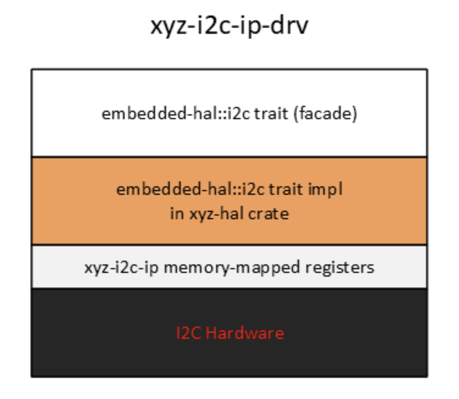
Proxy for a Kernel Mode Device Driver
In this section, we explore how a trait from the Device Development Kit (DDK) can enhance portability by decoupling the application writer from the underlying embedded stack.
The user of the peripheral is an application that is interacting with a kernel mode device driver via system calls, but is completely isolated from the underlying implementation.
This is applicable to any O/S with device drivers living in the kernel, like the Tock O/S.
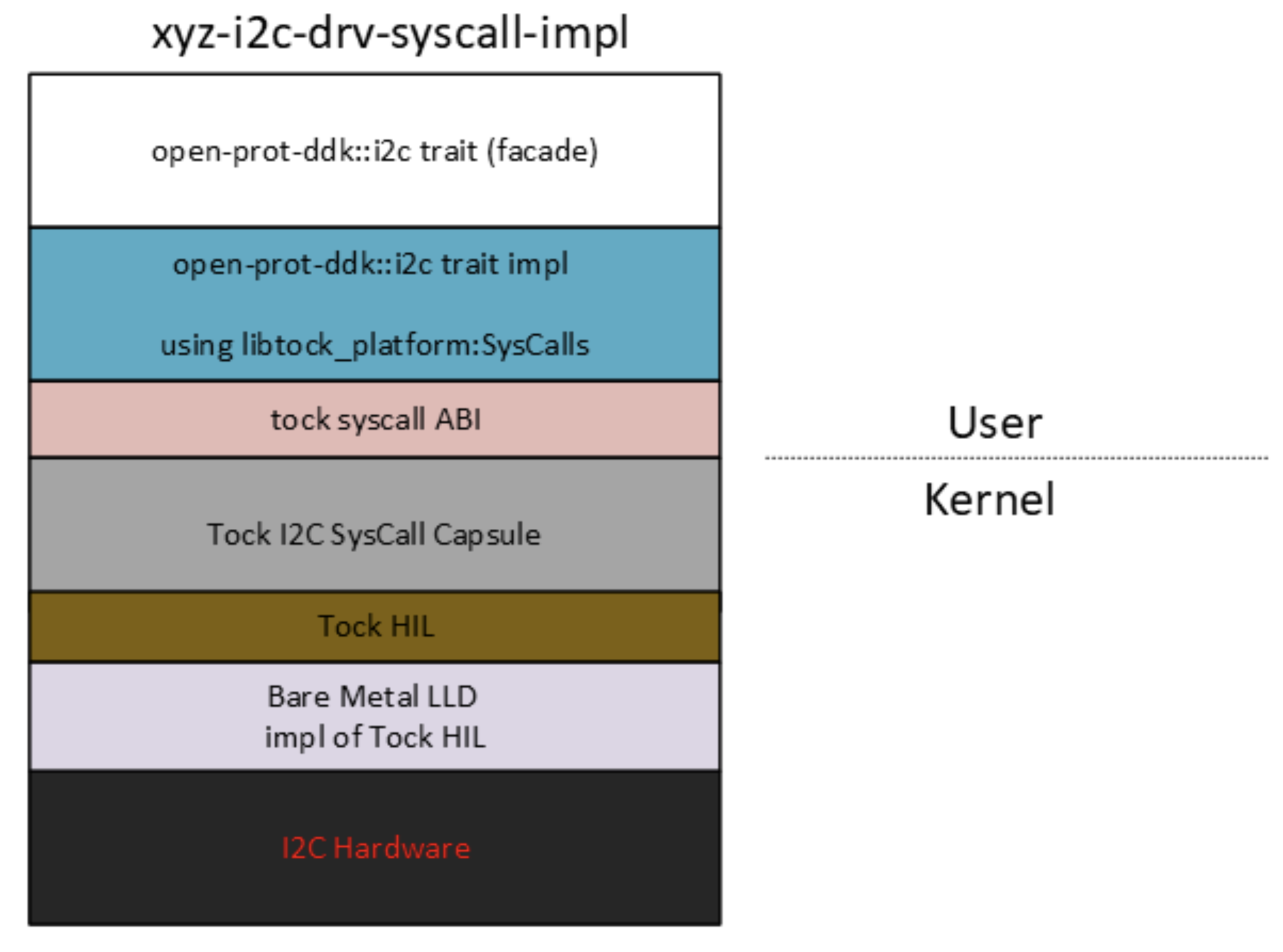
Proxy for a Peripheral Server Task
In this section, we will explore once more how traits from the Device Development Kit (DDK) can enhance portability by decoupling the application writer from the underlying Operating System architecture. This scenario is applicable to any microkernel-based O/S
The xyz-i2c-ipc-impl depicted below is distributed as a no_std driver crate
and is linked to a I2C client task. The I2C client task is an application that
is interacting with a user mode device driver, named the I2C server task via
message passing.
The I2C Server task owns the actual peripheral and is linked to a xyz-i2c-drv-imp driver crate, which is a low-level driver. .
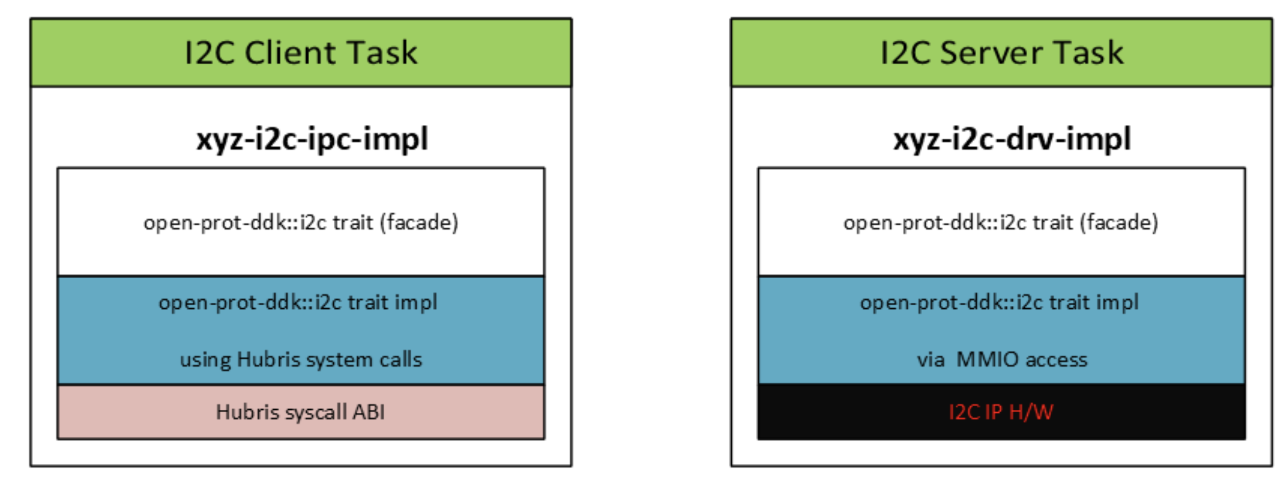
The I2C client task sends requests to the I2C peripheral owned by the server task via message passing, completely oblivious to the underlying implementation.
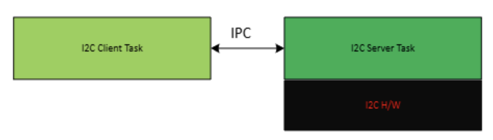
Terminology
The following acronyms and abbreviations are used throughout this document.
| Abbreviation | Description |
|---|---|
| AES | Advanced Encryption Standard |
| BMC | Baseboard Management Controller |
| CA | Certificate Authority |
| CPU | Central Processing Unit |
| CRL | Certificate Revocation List |
| CSR | Certificate Signing Request |
| CSP | Critical Security Parameter |
| DICE | Device Identifier Composition Engine |
| DRBG | Deterministic Random Bit Generator |
| ECDSA | Elliptic Curve Digital Signature Algorithm |
| FMC | FW First Measured Code |
| GPU | Graphics Processing Unit |
| HMAC | Hash-based message authentication code |
| IDevId | Initial Device Identifier |
| iRoT | Internal RoT |
| KAT | Known Answer Test |
| KDF | Key Derivation Function |
| LDevId | Locally Significant Device Identifier |
| MCTP | Management Component Transport Protocol |
| NIC | Network Interface Card |
| NIST | National Institute of Standards and technology |
| OCP | Open Compute Project |
| OTP | One-time programmable |
| PCR | Platform Configuration Register |
| PKI | Public Key infrastructure |
| PLDM | Platform Level Data Model |
| PUF | Physically unclonable function |
| RoT | Root of Trust |
| RTI | RoT for Identity |
| RTM | RoT for Measurement |
| RTRec | RoT for Recovery |
| RTU | RoT for Update |
| SHA | Secure Hash Algorithm |
| SoC | System on Chip |
| SPDM | Security Protocol and Data Model |
| SSD | Solid State Drive |
| TCB | Trusted Computing Base |
| TCI | TCB Component Identifier |
| TCG | Trusted Computing Group |
| TEE | Trusted Execution Environment |
| TRNG | True Random Number Generator |
Architecture
openprot is a no_std Rust firmware project for Platform Root-of-Trust
devices, organized as a Bazel module so that HAL traits, OS-abstraction
traits, OS-agnostic services, and target-specific glue can stay decoupled.
Repository layout
openprot/
├── MODULE.bazel              # Bazel module + crate_universe extensions
├── workflows.json            # Pigweed workflow groups (./pw …)
├── BUILD.bazel               # Top-level Bazel package
├── openprot/                 # Main application crate (lib.rs + main.rs)
├── drivers/
│   └── usart/                # Target-agnostic USART API, client, and server
├── hal/
│   ├── async/                # Async HAL trait crates
│   ├── blocking/             # Blocking HAL trait crates
│   └── nb/                   # Non-blocking (nb) HAL trait crates
├── platform/
│   ├── traits/               # OS-abstraction traits
│   └── impls/                # Concrete impls per host environment
├── services/
│   ├── i2c/                  # I2C API, IPC transports, and server runtime
│   ├── mctp/                 # MCTP API, transports, client, and server
│   ├── orchestrator/         # Boot orchestration, capabilities, and HAL adapters
│   ├── spdm/                 # SPDM requester, responder, and support crates
│   ├── storage/              # Storage service
│   └── telemetry/            # Telemetry service
├── target/
│   ├── ast10x0/              # ASPEED AST10x0 target, backends, and tests
│   ├── earlgrey/             # OpenTitan Earl Grey target
│   ├── mock/                 # Host/QEMU board data used by tests
│   └── veer/                 # Caliptra VeeR-EL2 target
├── third_party/
│   ├── pigweed/              # Pigweed integration
│   └── caliptra/             # caliptra-sw / caliptra-mcu-sw integration
├── presubmit/                # Python presubmit scripts
└── docs/                     # mdbook sources (this site)
The intent of the split is that hardware-facing contracts live under hal/
or a driver's public API, host-OS contracts live under platform/traits/, and
reusable protocol and service logic lives under services/. Concrete host
implementations belong in platform/impls/; silicon-specific backends,
peripherals, linker scripts, system images, and test runners belong under
target/. For example, drivers/usart/ defines a target-agnostic interface
while target/ast10x0/backend/usart/ implements it for AST10x0.
Interfaces, implementations, and protocols
The repository separates contracts from implementations so that protocol logic can be tested on a host without importing a device PAC or kernel:
hal/{async,blocking,nb}/contains hardware abstraction traits grouped by execution model. The blocking HAL includes interfaces for flash, GPIO, I2C, cryptography, key vaults, and system control.platform/traits/contains operating-system abstraction traits;platform/impls/contains concrete implementations for supported host environments.drivers/usart/{api,client,server}/separates the USART wire contract, client facade, and server dispatcher from its target backend.services/i2c/andservices/mctp/follow the same pattern: public API, platform-independent client/server logic, IPC adapters, and target-specific backends where required.services/spdm/builds requester and responder behavior on top of the MCTP transport and shared cryptographic support crates.
The README.md files in each driver or service directory document their
public seams, invariants, and host-test targets.
Build system
The build is driven by Bazel via Pigweed's workflow launcher; there is no Cargo workspace. The relevant pieces:
MODULE.bazeldeclares Bazel module dependencies (bazel_skylib,pigweed,platforms,rules_rust,rules_rust_mdbook,rules_python, pluscaliptra_depsanduregvia overrides).git_overridepins Pigweed to a specific upstream commit (MODULE.bazel:23-27), keeping the kernel/build/log/status/toolchain pieces reproducible.pw_rust.toolchainregisters Pigweed's managed Rust toolchains (MODULE.bazel:35-37); host C/C++ toolchains and therv32imcRISC-V C/C++ toolchain are registered viaregister_toolchains(MODULE.bazel:39-44).- Three
crate_universeworkspaces govern Rust crate dependencies:@rust_crates— cross-platform crates declared inthird_party/crates_io/Cargo.toml.@rust_caliptra_crates— embedded Caliptra crates (rv32imc, no std/alloc).@rust_caliptra_crates_host— Caliptra host tools (need std).
./pwisbazelisk run //:pw -- "$@"and dispatches to the named groups inworkflows.json(presubmit,default,ci,upstream_pigweed).
See usage.md for the everyday command surface and workflows.json for the
authoritative workflow definitions.
Pigweed integration
The veer target builds on Pigweed's microkernel and runtime crates:
@pigweed//pw_kernel— the microkernel running ontarget/veer/. Provides scheduling, IPC channels, interrupt objects, userspace isolation, and the#[entry]/#[process_entry]macros. System images are described declaratively insystem.json5files (seetarget/veer/for examples) and assembled by Pigweed'ssystem_image()macro.@pigweed//pw_log/rust:pw_log— structured logging used throughout userspace and target code.@pigweed//pw_status/rust:pw_status—Result<T, pw_status::Error>is the syscall and IPC return type.@pigweed//pw_toolchain/riscv_clang:riscv_clang_cc_toolchain_rv32imc— RISC-V C/C++ toolchain used by the veer target's mixed-language build.
For a concrete cross-process example, see design/pw-kernel-ipc.md and
target/veer/ipc/.
Targets
Each silicon/SoC target lives under target/<name>/ and provides its own
linker script, entry point, defs.bzl helpers, register definitions, and
test/runner tooling.
target/ast10x0/— ASPEED AST10x0. It contains board configuration, peripheral drivers, I2C and USART backends, PFR building blocks, and QEMU or hardware test harnesses. Run its executable QEMU tests withbazel test --config=virt_ast10x0 //target/ast10x0/....target/earlgrey/— OpenTitan Earl Grey. QEMU tests run on every PR; Verilator-driven tests are gated behind theverilatortag and the corresponding workflow group (seeworkflows.json).target/veer/— Caliptra VeeR-EL2. Built onpw_kerneland exercised on the Caliptra emulator viatarget/veer/tooling/caliptra_runner.bzl.
When adding a new target, prefer the target/<name>/defs.bzl helpers over
hand-rolled rust_binary rules, and always set target_compatible_with = TARGET_COMPATIBLE_WITH so wildcard host builds skip target-only crates.
Firmware images and tests
Reference firmware is assembled close to the target that supplies its
platform bindings. A target's system.json5 declares the process topology,
and Bazel system_image() rules combine that configuration with the kernel
and application crates. Examples include the AST10x0 USART client/server image
under target/ast10x0/tests/usart/ and the Earl Grey and VeeR syscall-latency
images under their respective target directories.
Host tests normally live next to the platform-independent API or service.
Emulator, simulator, and hardware-backed tests live under target/<name>/
alongside the runner and build configuration they require. This keeps host
wildcard tests from accidentally depending on target-only toolchains while
still exercising the same protocol codecs and dispatch logic used by firmware.
Third-party integration
third_party/pigweed/— local Pigweed integration including avisibility.patch.third_party/caliptra/— integration withcaliptra-swandcaliptra-mcu-sw. Version bumps go throughuprev.py, which writes bothversions.bzl(commit pins) and the CaliptraCargo.lockfiles.third_party/crates_io/— pinned crates.io dependencies for the main workspace;third_party/caliptra/crates_io/{embedded,host}/for the two Caliptra crate hubs.
Where to read next
coding-style.md— formatter configs and Rust conventions.contributing.mdanddevelopment-process.md— review and merge process.design/— focused notes on individual subsystems (e.g. pw_kernel IPC).
Coding Style
This document describes the coding style used by this project.
All of the formatters can be invoked by the pw utility script in the root of
the project:
$ ./pw format
Rust
This project follows the standard Rust Style
Guide for Rust code. Formatting is
done with rustfmt using the
rustfmt.toml
from the upstream Pigweed repository.
Beyond formatting, openprot is embedded, security-critical firmware and review
enforces the following constraints. See .github/copilot-instructions.md for
the full list.
no_stdonly. No heap types (Vec,String,HashMap,Box). Use fixed-size arrays andheaplesscollections.- Panic-free. No
unwrap,expect,panic!, or direct[]indexing in production paths. Preferget(), pattern matching, or returningResult/Option. - Checked arithmetic. Use
checked_*/saturating_*/wrapping_*rather than bare+,-,*on integers where overflow is possible. - Volatile MMIO. Register access uses
read_volatile/write_volatileand must go through HAL traits rather than touching registers directly. unsafeblocks require// SAFETY:comments that explain why the invariants hold.- Constant-time crypto. Use
subtlefor comparing secrets, andzeroizeto bound the lifetime of secret material in memory.
Python
This project follows PEP8 for Python code.
Formatting is done with the black formatter.
Starlark (bazel build system)
This project follows the standard bzl style
guide for Starlark code.
Formatting is done with the buildifier tool.
C / C++
This project follows the [Google C++ Style Guide] for C and C++ code, with the following exceptions:
- Indent is 4 spaces instead of 2.
- Function names should use
snake_caseinstead ofPascalCase. - In pointer declarations, the asterisk is attached to the variable name (
int *foo) instead of the type name (int* foo).
Formatting is done with clang-format.
Contributing to OpenPRoT
Thank you for your interest in contributing to the OpenPRoT project!
Contribution Process
Before you begin, please review our Development Process for details on our RFC process for large changes and our standard requirements for pull requests.
Contributor License Agreement
- Use of OpenPRoT requires no CLA.
- Contributions to OpenPRoT must have signed the CHIPS CLA.
Code of Conduct
The code of conduct can be found here.
Development Setup
- Clone the repository.
- Use the Pigweed workflow launcher
pworbazelfor common tasks:./pw presubmit- Run presubmit checks: formatting, license checks, C/C++ header checks, andclippy../pw format- Run the code formatters../pw ci- Build and run the host test suite../pw default- Build everything buildable on a dev host without running tests.bazel build //docs- Build documentation.
Firmware builds are driven per target platform. See the target's defs.bzl
for the Bazel flags and constraints used when building firmware for it.
Code Style
- Follow the coding style guide.
- Run
./pw presubmitto check for lints and ensure all tests pass.
Documentation
- Update documentation in the
docs/directory. - Build docs with
bazel build //docs. - Documentation is built with mdbook.
Issues
Please report issues on the GitHub issue tracker.
Development Process
This document describes the formal process for contributing changes to the OpenPRoT Project.
Types of Changes
There are two types of changes contributors may make:
- Small Change: Standard bug fixes, minor improvements, or documentation updates.
- [Optional] File a lightweight GitHub issue.
- Submit a pull request (PR) with the change.
- Wait for project maintainers to approve and merge.
- Large Change: Substantial changes that require a Request for Comment (RFC).
- Draft an RFC (a GitHub issue titled "[RFC] …") describing the proposed change.
- Seek commentary from project contributors.
- Seek approval from the OpenPRoT Technical Steering Committee (TSC).
- Update the RFC based on feedback.
- Submit one or more pull requests to implement the approved RFC.
Process Flow
graph TD
    Start((Proposal)) --> Type{Type?}
    Type -- Small --> SmallImpl[Implement]
    SmallImpl --> SmallIssue[Optional: File Issue]
    SmallIssue --> SmallPR[Submit PR]
    SmallPR --> SmallApprove[Approval]
    SmallApprove --> SmallMerge[Merge]
    Type -- Large --> LargeRFC[Draft RFC]
    LargeRFC --> LargeDiscuss[Discussion]
    LargeDiscuss --> LargeTSC[Approval - TSC]
    LargeTSC --> LargeUpdate{Changes?}
    LargeUpdate -- Yes --> LargeRFCUpdate[Update RFC]
    LargeRFCUpdate --> LargeDiscuss
    LargeUpdate -- No --> LargeImpl[Implement]
    LargeImpl --> LargePR[Submit PR]
    LargePR --> LargeApprove[Approval]
    LargeApprove --> LargeMerge[Merge]
    LargeMerge -. Loop for multiple PRs .-> LargeImpl
What constitutes a "Large" change?
A large change is loosely defined as any change that substantially impacts:
- Architecture: Adding a new component, module, or drastically changing an existing one.
- Boot process: Changes to the firmware initialization or secure boot sequence.
- API: Command sets, register layout changes (as defined in firmware drivers), or I/O interface changes.
- Security Posture: Changes to the threat model, attestation mechanisms, or cryptographic implementations.
- Maintenance: Significant tool changes or environment updates.
If a contributor is unclear whether a change is "small" or "large," they should start by filing a GitHub issue for guidance.
Structure of an RFC
To streamline the review of large changes, all RFCs must be submitted as a GitHub Issue with a title prefixed by "[RFC]". The body must detail:
- Scope: What parts of the project will be affected.
- Rationale: The motivation and justification for the change.
- Implementation Tradeoffs: Details of various implementations being considered.
- Implementation Timeline: A realistic estimate for completion.
- Test Plan: Required for any security-critical or architectural changes to ensure quality and maintainability.
- Maintenance: The individual or team responsible for the feature's future maintenance.
RFC Approval Authority
Final approval authority for all RFCs rests with the OpenPRoT TSC. Once the TSC approves an RFC, corresponding PRs can be submitted for review. Implementation may begin on a fork for experimentation, but PRs should not be submitted to the upstream repository until approval is granted.
Implementation
Additional Requirements for Contribution
To ensure quality and maintainability, all contributions must adhere to these rules:
- Documentation: Updates must describe new functionality and usage.
- Cryptographic Hardening: Changes to cryptographic modules must include a thorough test plan.
- Tool Compatibility: All validation plans and features must be compatible with existing supported tools and versions.
Submission of Pull Requests
All contributions must follow the standard GitHub fork-and-PR methodology. Large features should be submitted via multiple, smaller PRs (ideally fewer than 500 lines of code) to reduce the burden of review.
References
This process is adapted from the Caliptra Contributing Process.
Design
This section contains design documents that provide a detailed overview of the design and implementation of the OpenProt project. These documents are intended to provide guidance to developers and anyone interested in the internal workings of the project.
Documents
- Pigweed Integration Overview: What openprot
consumes from Pigweed (
pw_kernel,pw_log,pw_status, toolchains, crate universe, the./pwlauncher) and where each piece is pinned. - pw_kernel IPC: How to declare and use channel
objects to communicate between two
pw_kerneluserspace processes. Worked example lives attarget/veer/ipc/. - Orchestrator: The eRoT boot-sequence state
machine (
services/orchestrator/sm). Covers the two-tier firmware verification model (ComponentAttrs, eRoT gate, iRoT gate), the verification boundary, and the full state/transition table.
Pigweed Integration Overview
OpenPRoT uses Pigweed for its build infrastructure,
kernel, logging, and shared Result type. This page summarizes what comes
from Pigweed, where it is pinned, and which OpenPRoT directories consume it.
Pinning
Pigweed is a Bazel module dependency pinned to an explicit upstream commit:
# Example from MODULE.bazel
bazel_dep(name = "pigweed")

git_override(
    module_name = "pigweed",
    commit = "cf8b16a4fbf7bc6cb76b804acd510c7cb3adf995",
    remote = "https://pigweed.googlesource.com/pigweed/pigweed",
)
See MODULE.bazel. Use the canonical pigweed.googlesource.com remote when
reading upstream. The GitHub mirror is read-only and not the authoritative
source.
What OpenPRoT uses
pw_kernel - microkernel
OpenPRoT uses pw_kernel as its microkernel. The kernel provides scheduling,
IPC channels, interrupt objects, userspace isolation, and the #[entry] /
#[process_entry] macros used by application code. System images are
described declaratively in system.json5 files and assembled by Pigweed's
system_image() macro.
pw_log - structured logging
@pigweed//pw_log/rust:pw_log is the logging surface used throughout
userspace and target code.
pw_status - shared result type
@pigweed//pw_status/rust:pw_status provides pw_status::Error and the
Result<T, pw_status::Error> alias that every syscall and IPC entry point
returns. The error variants map cleanly to the kernel's rejection reasons
(InvalidArgument, Internal, DeadlineExceeded, …).
Toolchains
Pigweed owns both the Rust and C/C++ toolchains used by the build:
- Rust toolchain is registered via the
pw_rustmodule extension;pw_rust_toolchains//:allis registered as a Bazel toolchain. - Host C/C++:
@pigweed//pw_toolchain/host_clang:host_cc_toolchain_linuxand@pigweed//pw_toolchain/host_clang:host_cc_toolchain_macos. - RISC-V C/C++ for the OpenPRoT target:
@pigweed//pw_toolchain/riscv_clang:riscv_clang_cc_toolchain_rv32imc.
Crate universe override
Pigweed ships its own rust_crates extension for crates its Rust code uses.
Upstream's default set does not currently include
riscv32imc-unknown-none-elf, so OpenPRoT overrides the Pigweed repo to
point at its own @rust_crates workspace.
./pw workflow launcher
./pw is a shell wrapper around bazelisk run //:pw -- "$@". It dispatches
to the named groups defined in workflows.json:
./pw presubmit- format check, license check, clippy aspect build../pw default- wildcard build with hardware/disabled filtered out../pw ci- CI test suite, same exclusions plus-verilator../pw upstream_pigweed-ciplus the Earlgrey verilator tests.
See workflows.json for the group definitions and usage.md for the everyday
command surface.
Where to go next
design/pw-kernel-ipc.md- concretepw_kernelIPC walkthrough.usage.md-./pwandbazelcommand reference.architecture.md- how the Pigweed pieces slot into the openprot tree.
pw_kernel IPC: Channel Objects
This guide explains how to wire up cross-process communication between two
pw_kernel userspace processes using channel objects.
A worked example lives at target/veer/ipc/ (system image) and upstream at
@pigweed//pw_kernel/tests/ipc/user/ (the two processes themselves) — refer
to those files alongside this document.
Conceptual model
A channel in pw_kernel is a kernel object with two endpoints owned by
distinct processes:
- A handler endpoint — the server side. It waits for an incoming message, reads the request, and sends a single response.
- An initiator endpoint — the client side. It performs a single
channel_transactcall that sends a request and blocks until the handler responds.
The kernel handles the rendezvous, copies the request and response between process address spaces, and wakes the appropriate thread on each side.
Declaring the channel in system.json5
Channel endpoints are declared as objects inside the processes list of
the system.json5 file driving the system image. Each side names its local
object; the initiator names the handler process and its handler-side object
name to wire the two together.
{
  apps: [
    {
      name: "ipc",
      flash_size_bytes: 32768,
      ram_size_bytes: 8192,
      processes: [
        {
          name: "initiator",
          objects: [
            {
              name: "IPC",
              type: "channel_initiator",
              handler_process: "handler",
              handler_object_name: "IPC",
            },
          ],
          threads: [
            { name: "initiator thread", stack_size_bytes: 1024 },
          ],
        },
        {
          name: "handler",
          objects: [
            { name: "IPC", type: "channel_handler" },
          ],
          threads: [
            { name: "handler thread", stack_size_bytes: 1024 },
          ],
        },
      ],
    },
  ],
}
The system_generator codegen step turns the name field into a
handle::IPC constant inside each process's generated *_codegen crate.
The two name strings do not need to match across processes; only the
handler_object_name linkage on the initiator does.
Initiator side
The initiator performs a synchronous channel_transact: it provides a send
buffer, a receive buffer, and a deadline, and the syscall returns the number
of bytes the handler wrote.
#![allow(unused)]
fn main() {
use initiator_codegen::handle;
use pw_status::Result;
use userspace::time::Instant;
use userspace::{process_entry, syscall};

fn send_one(c: char) -> Result<()> {
    let mut send_buf = [0u8; size_of::<char>()];
    let mut recv_buf = [0u8; size_of::<char>() * 2];

    c.encode_utf8(&mut send_buf);
    let _len: usize = syscall::channel_transact(
        handle::IPC,
        &send_buf,
        &mut recv_buf,
        Instant::MAX,
    )?;
    Ok(())
}

#[process_entry("initiator")]
fn entry() -> ! {
    let _ = send_one('a');
    loop {}
}
}
Instant::MAX waits indefinitely. Pass a finite Instant to bound the
transaction — the kernel returns a deadline-exceeded error rather than
blocking forever.
Handler side
The handler waits for the channel to become readable, reads the request,
and writes a response. The pattern is object_wait → channel_read →
channel_respond, looped.
#![allow(unused)]
fn main() {
use handler_codegen::handle;
use pw_status::{Error, Result};
use userspace::process_entry;
use userspace::syscall::{self, Signals};
use userspace::time::Instant;

fn handle_messages() -> Result<()> {
    loop {
        let wait = syscall::object_wait(handle::IPC, Signals::READABLE, Instant::MAX)
            .map_err(|_| Error::Internal)?;
        if !wait.pending_signals.contains(Signals::READABLE) {
            return Err(Error::Internal);
        }

        let mut request = [0u8; size_of::<char>()];
        let _len = syscall::channel_read(handle::IPC, 0, &mut request)?;

        let c = char::from_u32(u32::from_ne_bytes(request))
            .ok_or(Error::InvalidArgument)?;
        let upper = c.to_ascii_uppercase();

        let mut response = [0u8; size_of::<char>() * 2];
        upper.encode_utf8(&mut response[0..size_of::<char>()]);
        c.encode_utf8(&mut response[size_of::<char>()..]);
        syscall::channel_respond(handle::IPC, &response)?;
    }
}

#[process_entry("handler")]
fn entry() -> ! {
    if let Err(e) = handle_messages() {
        let _ = syscall::debug_shutdown(Err(e));
    }
    loop {}
}
}
channel_respond must be called exactly once per request; the next
object_wait then unblocks for the following request.
Build wiring on the openprot side
On a target like veer, the system_image macro consumes both the
system.json5 and the upstream multi_process_app target that bundles the
two process binaries. See target/veer/ipc/user/BUILD.bazel:
system_image(
    name = "ipc",
    apps = ["@pigweed//pw_kernel/tests/ipc/user:ipc"],
    kernel = ":target",
    platform = "//target/veer",
    system_config = ":system_config",
    tags = ["kernel"],
)

target_codegen(
    name = "codegen",
    arch = "@pigweed//pw_kernel/arch/riscv:arch_riscv",
    system_config = ":system_config",
)
Each process's own BUILD.bazel (upstream, in
@pigweed//pw_kernel/tests/ipc/user/BUILD.bazel) uses the rust_process
macro and names its codegen crate via codegen_crate_name, which is what
allows use initiator_codegen::handle and use handler_codegen::handle to
resolve from within the source files.
Designing your own channel protocol
The kernel does not impose a wire format on the request or response — both are byte buffers. A few rules of thumb that follow from that:
- Pick a fixed-size request/response layout (or a length-prefixed one) so
the handler can size its read buffer up front. Keep the buffers on the
stack — they live inside
no_stduserspace. - Validate everything coming off the wire: length, range, enum variants. Treat the request side as untrusted — it is in a different process and may be running independently maintained code.
- Keep the handler loop free of
unwrap/ panic paths. The handler is the service for every other process holding an initiator endpoint, so a panic-on-malformed-input becomes a denial-of-service. - For typed payloads, define a small request/response enum in a shared
crate that both processes depend on, and use a byte-stable encoding
(e.g.
zerocopy) — there is no built-in IDL.
Limitations to know about
- A channel has exactly one initiator and one handler. To fan in multiple
clients, declare multiple channel pairs all pointing at the same handler
process and have the handler
object_waiton each in turn. - The handler must call
channel_respondexactly once perchannel_readbefore reading again. Skipping the response leaves the initiator blocked. - Bounded-deadline transactions require the caller to pass a finite
Instant; the kernel does not impose a default timeout.
Orchestrator State Machine
The orchestrator is the eRoT's boot-sequence controller. It walks the platform trust chain — verifying each component's firmware and releasing it from reset in order — and then governs the operational lifecycle (attestation, firmware update, corruption recovery).
It lives in services/orchestrator/sm as a pure state machine: it never touches
hardware directly. Every action is described as an [Effect] value that the
surrounding platform carries out; every piece of outside information arrives as an
[Event]. This keeps the core testable without hardware and free of I/O.
State Topology
The reachable states, the events (with guards) that drive transitions between them, and the effects each transition emits are all shown in the full state diagram in State Machine. That diagram is the single source of truth for the topology; it is not duplicated here to avoid the two drifting apart.
Documents
- Verification Model: The two-tier firmware
verification model (eRoT gate + optional iRoT gate), the verification
boundary,
ComponentAttrs, and concrete sequencing examples. - State Machine: All states, shared storage, entry
actions, transition table, and the
SupervisingPlatformsuperstate. - Platform Architecture: The platform half around the core — surrounding services, capability contracts, the board device table, and the fail-safe rules at the responsibility boundary.
Design Principles
Effects, not actions; reads as events. Handlers only call
ctx.emit(Effect::…) to describe what should happen, and receive every piece of
outside information in event payloads — the core never reads flash, drives a
GPIO, opens a channel, or touches a provisioning store. The full core/platform
split is the Platform Boundary
in the Verification Model.
Feedback as data. Internal follow-up signals (e.g. the retry-cap lockdown
RecoveryFailed) are emitted as Effect::Emit(event). The orchestrator queues
and handles them immediately, making them visible in the effect trace rather than
hiding them as implicit state changes. See the
Recovering state for a worked example.
Board-supplied policy. The core hard-codes no deployment-specific values. The platform supplies the trust chain (component ids, kinds, and required/optional policy) and the recovery-retry cap at startup.
Relationship to CSA Architecture
The state machine is a direct implementation of the boot sequence described in the CSA architecture document:
| CSA concept | State machine encoding |
|---|---|
| eRoT holds component in reset until firmware verified | PreSupervision emits ReleaseReset only on VerificationPassed |
| Component with Caliptra iRoT requires two independent checks | ComponentKind::Active → AwaitingReady until ComponentReady |
| Passive component (no iRoT): eRoT check only | ComponentKind::Passive → advance immediately after ReleaseReset |
| Isolable component: failure skips, not blocks | FailurePolicy::Isolable → skip (held in reset); advance without Recovering; no cascade |
| Cascading skip: failure also holds dependents | FailurePolicy::Cascading + ComponentAttrs::depends_on → cascade-skip via statuses (Isolated) |
| Boot-progress watchdog: component must signal readiness in time | Timeout(ComponentId) event → AwaitingReady → Recovering |
| Recovery scope groups components that restore together | ComponentAttrs::recovery_region (RegionId) → platform restores full region on RestoreGoldenImage |
Applicability Across Admissible Architectures
The orchestrator is eRoT-scoped: one instance runs per discrete eRoT chip
running OpenPRoT firmware. The same crate and binary are used at every such
tier — the only difference between deployments is the chain configuration
supplied at startup. eRoT chips not running OpenPRoT (e.g. a third-party AMC
or a legacy DC-SCM implementation) appear as opaque ComponentId entries in
the chain of the nearest OpenPRoT eRoT above them.
Model 1 — Module (single PCIe add-in card): a discrete eRoT is optional.
When present, it runs one orchestrator instance with a short chain containing
the card's SoC. When absent, the module relies on the parent node's eRoT
instance to verify and release it as a ComponentId in the node's chain.
Model 2 — Single Node Compute: the DC-SCM discrete eRoT runs one orchestrator instance whose chain covers all critical node devices (CPU, BMC, NIC, storage). This is the canonical single-instance deployment.
Model 3 — Complex Heterogeneous Compute: the three-tier hierarchy maps to independent orchestrator instances at each tier:
- Each AMC / EAM (subsystem eRoT) runs one instance whose chain covers the GPU or AI accelerator devices it manages.
- The DC-SCM node eRoT runs one instance whose chain covers CPUs, BMC, SmartNICs, storage, and the AMC/EAM chips themselves.
The node eRoT treats each AMC/EAM as just another ComponentId — Active if
the AMC has its own integrated iRoT, Passive if not. It has no visibility
into the AMC's internal chain walk; it only observes the AMC's
VerificationPassed / ComponentReady signals, like any other component.
| Admissible Architecture | Orchestrator instances | Chain scope per instance |
|---|---|---|
| Module (eRoT present) | 1 | Card SoC |
| Module (no eRoT) | 0 | — (verified by parent node eRoT) |
| Single Node Compute | 1 | All node critical devices |
| Complex Heterogeneous Compute | 1 per subsystem eRoT + 1 node eRoT | Subsystem devices / all node devices including subsystem eRoTs |
Verification Model
This document describes how platform firmware verification is modelled in the
orchestrator state machine (services/orchestrator/sm): the problem it solves,
the types that carry the domain, the states that sequence the work, and the
boundary between the pure core and the platform that executes it.
1. The Problem
The eRoT (external Root of Trust — the discrete RoT device, e.g. on a DC-SCM) must verify every platform component's firmware before releasing it from reset. Two independent mechanisms do this:
-
eRoT-side: the eRoT reads the component's firmware image from the SPI flash it controls, verifies the signature and SVN against a Reference Integrity Manifest (RIM/PFM), and only then releases the component from reset.
-
iRoT-side: components with an integrated Root of Trust (e.g. a BMC SoC or CPU with Caliptra) perform their own independent local self-verification after reset. The eRoT must wait for this local check to complete before treating the component as trusted and advancing to the next one in the chain.
Components that have no integrated iRoT (e.g. a NIC) rely solely on the eRoT-side check. The eRoT can advance immediately after releasing them.
This two-tier model — eRoT gate + optional iRoT gate — is the core problem the verification states solve. It is grounded directly in the CSA architecture boot sequence: "The eRoT and the iRoT provide complementary guarantees: the eRoT controls whether a component is released from reset; the iRoT controls whether the component's own firmware executes."
The verification boundary is the interface between the platform and the
pure state-machine core. Only verdicts cross it: the platform performs all
cryptographic work (reading flash, checking signatures and SVN) and then signals
the outcome via an event. The core never sees raw firmware data or hash values —
it only acts on the resulting VerificationPassed or VerificationFailed. This
keeps the core free of I/O and testable without hardware.
2. Domain Types
ComponentKind
Classifies the iRoT gate for a component. Supplied by the platform at chain-build time; the core never derives it.
Active  — has an integrated iRoT (e.g. Caliptra); both eRoT and iRoT checks apply
Passive — no integrated iRoT; only the eRoT check applies
In CSA terminology: Active corresponds to a SoC with an integrated iRoT
(e.g. a BMC or CPU with Caliptra). Passive corresponds to a symbiont device
— per NIST SP 800-193 §3.4, a device that lacks the capability to perform its
own firmware verification and relies on an external RoT (the eRoT, or an
intermediate RoT in a tiered model) to do so on its behalf.
FailurePolicy
Determines what the orchestrator does when a component's firmware fails verification.
Required   — attempt recovery; re-walk the chain after `Restored`; latch
             `Locked` if the retry cap is reached
Isolable   — hold the component in reset; advance past it; continue the walk
Cascading  — same as Isolable, and additionally hold in reset any component
             whose `depends_on` names this one
RegionId
An opaque u8 that groups components into a recovery region. Components
assigned the same RegionId must be restored together; when any region member
triggers Recovering, the platform issues a joint restore operation for the
entire region. The core treats the id as an equality key only and never
inspects the membership.
ComponentAttrs
Per-component attributes:
#![allow(unused)]
fn main() {
pub struct ComponentAttrs {
    pub kind: ComponentKind,              // iRoT gate: Active | Passive
    pub failure_policy: FailurePolicy,    // verification-failure handling
    pub recovery_region: RegionId,        // which components are recovered together
    pub depends_on: Option<ComponentId>,  // cascade trigger: held if named component was skipped
}
}
failure_policy | VerificationFailed behaviour |
|---|---|
Required | → Recovering; component held in reset; chain walk halts until restored |
Isolable | component held in reset; cursor advances; chain walk continues; no cascade to dependents |
Cascading | component marked Isolated (held in reset); any component whose depends_on matches this id is also marked Isolated and skipped; cursor advances; chain walk continues |
A component that fails verification is never released from reset regardless of its failure policy — releasing a component whose firmware failed verification would mean running untrusted code, which breaks the trust invariant.
depends_on is only meaningful when the named component has FailurePolicy::Cascading.
Only Cascading-failed components (and their transitively cascade-skipped dependents)
are marked Isolated. Before emitting ReadFirmware for any component, the core
checks whether its depends_on names a component already marked Isolated; if so, the
depending component is also held in reset and marked Isolated without emitting
ReadFirmware or VerifyFirmware. This check repeats for each newly-isolated
component's successors until no further cascade is triggered. An Isolable failure
skips only the failed component; it marks nothing else Isolated and causes no
downstream cascade.
Convenience constructors: ComponentAttrs::active_required(),
passive_required(), active_isolable(), passive_isolable(),
active_cascading(), passive_cascading().
ComponentId
An opaque u8 the core carries and equality-compares but never inspects. The
platform decides which id maps to which physical device.
Events that cross the verification boundary
| Event | Direction | Meaning |
|---|---|---|
VerificationPassed(ComponentId) | platform → core | The eRoT-side check passed: signature and SVN valid. |
VerificationFailed(ComponentId) | platform → core | The eRoT-side check failed: image rejected. |
ComponentReady(ComponentId) | platform → core | An Active component's integrated iRoT has finished its local verification and the component is operational (e.g. MCTP channel established). |
Timeout(ComponentId) | platform → core | The platform's watchdog fired: the named Active component did not deliver ComponentReady within the platform-policy window. The platform arms the watchdog after emitting ReleaseReset and cancels it on ComponentReady. Treated as a verification failure for recovery purposes. |
Effects the core emits for verification work
| Effect | Meaning |
|---|---|
ReadFirmware(ComponentId) | Ask the platform to read the component's firmware image from eRoT-controlled flash. |
VerifyFirmware(ComponentId) | Ask the platform to verify the image against the RIM/PFM. The platform responds with VerificationPassed or VerificationFailed. |
ReleaseReset(ComponentId) | Release the named component from reset. Emitted only after VerificationPassed. |
These are descriptions, not actions. The platform's Platform::execute carries
them out; the core never touches hardware.
3. Sequencing by ComponentAttrs
Active → Passive (happy path)
chain: [(C0, {Active, Required}), (C1, {Passive, Required})]

PreSupervision (entry):
  emit ReadFirmware(C0)
  emit VerifyFirmware(C0)

VerificationPassed(C0):           ← eRoT check done
  emit ReleaseReset(C0)
  emit ReadFirmware(C1)           ← speculative eRoT check of next
  emit VerifyFirmware(C1)
  cursor = 1, awaiting = Some(C0)
  → AwaitingReady

ComponentReady(C0):               ← C0's iRoT done
  awaiting = None
  Handled (stay in AwaitingReady, wait for VerificationPassed(C1))

VerificationPassed(C1):           ← speculative eRoT check resolved
  emit ReleaseReset(C1)
  chain done → Ready
Isolable component failure (skip, continue)
chain: [(BMC, {Active, Required}), (NIC, {Passive, Isolable})]

VerificationPassed(BMC):
  emit ReleaseReset(BMC)
  emit ReadFirmware(NIC)
  emit VerifyFirmware(NIC)
  awaiting = Some(BMC) → AwaitingReady

VerificationFailed(NIC):          ← NIC firmware rejected; Isolable → skip
  NIC stays held in reset
  cursor advances past end
  awaiting is still Some(BMC) → stay in AwaitingReady

ComponentReady(BMC):              ← BMC iRoT done; cursor past end → Ready
  awaiting = None → Ready
Concrete example: BMC (Active, required) → HOST (Active, required) → NIC (Passive, optional)
This matches the CSA single-node boot sequence.
chain: [(BMC, {Active, Required}), (HOST, {Active, Required}), (NIC, {Passive, Isolable})]

PreSupervision (entry):
  emit ReadFirmware(BMC)
  emit VerifyFirmware(BMC)          ← eRoT reads and checks BMC firmware from SPI flash

VerificationPassed(BMC):            ← eRoT: BMC firmware signature + SVN valid
  emit ReleaseReset(BMC)            ← eRoT releases BMC from reset; Caliptra iRoT runs
  emit ReadFirmware(HOST)           ← speculative: eRoT starts HOST firmware check
  emit VerifyFirmware(HOST)           while BMC's Caliptra iRoT is still booting
  cursor = 1, awaiting = Some(BMC)
  → AwaitingReady

ComponentReady(BMC):                ← BMC Caliptra iRoT done; MCTP channel up
  awaiting = None
  Handled (still in AwaitingReady, waiting for VerificationPassed(HOST))

VerificationPassed(HOST):           ← eRoT: HOST firmware signature + SVN valid
  emit ReleaseReset(HOST)           ← eRoT releases HOST from reset; Caliptra iRoT runs
  emit ReadFirmware(NIC)            ← speculative: eRoT starts NIC firmware check
  emit VerifyFirmware(NIC)            while HOST's Caliptra iRoT is still booting
  cursor = 2
  Handled (stay in AwaitingReady — still waiting on ComponentReady(HOST) and/or NIC result)

ComponentReady(HOST):               ← HOST Caliptra iRoT done; BIOS/UEFI executing
  awaiting = None
  Handled

VerificationPassed(NIC):            ← eRoT: NIC firmware valid (Passive — no iRoT gate)
  emit ReleaseReset(NIC)
  chain done → Ready
If NIC fails verification instead:
VerificationFailed(NIC):            ← NIC Isolable → skip; NIC stays held in reset
  cursor = 3 (past end)
  awaiting = None (already cleared by ComponentReady(HOST))
  → Ready
4. The Speculative Read Pattern
When an Active component passes eRoT verification the core does three things
in the same handler, before transitioning to AwaitingReady:
emit ReleaseReset(current)
emit ReadFirmware(next)        ← speculative: next eRoT check starts immediately
emit VerifyFirmware(next)      ← while current's iRoT is still booting
cursor += 1
awaiting = Some(current)
→ Transition(AwaitingReady)
This overlaps the integrated iRoT boot time of the current component with the eRoT firmware read of the next. The two checks are independent (different hardware paths), so the overlap is safe.
Deliberate divergence from the CSA boot sequence diagram. The CSA diagram
shows strictly sequential ordering — for example, the BMC MCTP channel is
established before the eRoT begins reading the CPU firmware. The
speculative-read pattern departs from this: the eRoT starts the next
component's firmware read as soon as the current one is released from reset,
without waiting for ComponentReady. The trust guarantee is fully preserved:
ReleaseReset for the next component is never emitted until that component's
own VerificationPassed arrives. The overlap reduces boot time on real
hardware where iRoT initialization can take several seconds.
5. Recovery Is a Re-boot
A firmware check is only meaningful while its component is held in reset. This
is a CSA/NIST principle, not an orchestrator invention: corruption detection is
defined at boot and at rest, both operating on the firmware image in NVM
rather than on running code, and "the eRoT holds each downstream component in
reset until verification is complete and then releases it" — "no component
executes unverified firmware" (CSA boot sequence; NIST SP 800-193 Protection
and Recovery). The reason is concrete: if a component is already executing, the
verdict says nothing about the code actually running — a live component can be
running something other than what is in flash, and can rewrite its own flash the
instant after the check passes. VerifyFirmware is therefore an at-rest
operation, and the initial power-on walk is sound only because the platform
holds every component in reset at power-on and the core releases each one
(ReleaseReset) solely after its own VerificationPassed.
Recovery re-runs that walk, so it must re-establish the same precondition. CSA grounds this too: recovery activates through a reset — its Recovery Sequence ends by marking the recovered slot as the boot target and initiating a reset or slot-switch, so a recovered component always re-enters service from a held, freshly-verified state rather than being patched live.
Design decision (orchestrator-specific): CSA describes recovery per
device — write the recovery image to the failed slot, reset that device. This
orchestrator goes further: on re-entering PreSupervision the core first
asserts reset on every non-isolated component, then walks the whole chain
from a fully-held state and re-releases each part in order. Quiescing the entire
chain (not just the failed device) is our choice, not a verbatim CSA
requirement; it follows from the at-rest principle and buys two things — a
single verification path shared with power-on, and the removal of any foothold a
compromised neighbor may have gained after it was released. The result is one
invariant:
Every running component was verified while held in reset, immediately before it was released, since the most recent full walk. No live component is ever re-verified.
Re-verifying a still-live sibling from a previous walk would be meaningless: its earlier pass belongs to a walk that is over, and nothing has held it at rest since. Recovery returns the platform to a known-held state and rebuilds trust from there, exactly as power-on does.
The strength of this rests on a platform-side precondition on AssertReset; see
§6.
6. The Platform Boundary
The orchestrator is split into a pure core and the platform that hosts
it. The core is a deterministic state machine: it receives an Event, updates its
own in-memory state, and appends Effect descriptions to a write-only Sink.
It performs no I/O, reads no hardware, and cannot observe the result of any
effect except as a future Event. Everything that touches the world — flash,
reset lines, transports, timers, measurement results — lives in the platform.
graph LR
    subgraph WORLD ["World  (board / platform)  —  examples/board.rs"]
        W1["reads OTP/UFM<br/>hardware IRQs<br/>measurement results"]
        W2["Platform::execute<br/>drives flash / reset<br/>SPI / I3C / MCTP"]
    end

    subgraph CORE ["Pure Core  —  src/lib.rs"]
        ORCH["Orchestrator<br/>dispatch loop"]
        SM["StateMachine<br/>Rot shared storage<br/>State handlers<br/>Operational superstate"]
        SINK["Sink<br/>append-only effect buffer<br/>cannot read or do IO"]
        ORCH --> SM
        SM -->|"ctx.emit"| SINK
    end

    W1 -->|"Event"| ORCH
    SINK -->|"Effect<br/>drained after each dispatch"| W2
Only two value types cross the boundary, and they cross in opposite directions:
Event(world → core) — the platform's report of something that already happened: a verdict (VerificationPassed/Failed), a readiness signal (ComponentReady), a timer expiry (Timeout), or a power-on result. Events are the only way the core learns anything about the world.Effect(core → world) — a description of work the platform should perform:ReadFirmware,VerifyFirmware,ReleaseReset,RecoverComponent, and so on. Effects are inert data; the core never waits on them and never sees them succeed or fail directly.
This inversion is what keeps the core testable without hardware: a test drives
Events in and asserts on the Effects that come out, with no flash, no
transports, and no clocks. It also fixes where mechanism lives. The core
names what must happen to which component; the platform decides how.
For example, Effect::RecoverComponent(id) says only "recover this component" —
whether that resolves to a golden-image restore, an A/B slot swap, a streamed
image, or a vendor-specific scheme is a platform/configuration decision, never
encoded in the core.
The core never reads flash, never checks signatures, never observes reset lines. It only emits descriptions. The complete split:
| Responsibility | Core (sm/src/lib.rs) | Platform (Platform impl) |
|---|---|---|
Chain order and ComponentAttrs | reads from Rot.chain, set by platform at startup | decides and provides |
| Read firmware image | emits ReadFirmware(id) | executes: eRoT reads via SPI interposition, I3C, or other transport |
| Verify signature / SVN | emits VerifyFirmware(id) | executes: eRoT checks against RIM/PFM; responds with VerificationPassed or VerificationFailed |
| Release from reset | emits ReleaseReset(id) | executes: eRoT drives reset GPIO or equivalent |
| Detect iRoT readiness | waits for ComponentReady(id) event | observes: integrated iRoT signals readiness (MCTP channel-up, GPIO, etc.); calls dispatch |
| Per-component failure policy | checks attrs.failure_policy in handler | none — policy is encoded in the chain at startup |
| Cascade-skip evaluation | checks attrs.depends_on against the Isolated components in statuses before emitting ReadFirmware | encodes the dependency graph at chain-build time |
| Recovery region membership | reads attrs.recovery_region when entering Recovering | assigns each component to a region at chain-build time |
Reset must hold until release. The core only emits the ordering of
AssertReset and ReleaseReset; it relies on the platform to make
AssertReset durable — a held quiesce, not a pulse — and to guarantee that no
component executes between its reset assertion and its post-verification
ReleaseReset. This is what makes an at-rest check meaningful, and it is the
precondition the recovery re-boot (§5) depends on.
The core is policy-free. It carries no tunable policy and no mechanism of its own — every policy input is either board-supplied config data or arrives as an event:
- Failure handling is data-driven. The handlers read each component's
FailurePolicyfrom the chain and branch on it; nothing is hardcoded. Fail-open vs fail-close is therefore a per-component configuration choice (Required= fail-close;Isolable/Cascading= fail-open), set at chain-build time. - The retry cap is supplied, not baked in.
max_retryis a constructor argument, not a constant. - Timing lives outside. The core sets no durations;
TimeoutandCommitTimeoutarrive as events from the platform's watchdogs. The core only decides whether a given timeout is actionable. - Mechanism is deferred. Effects name what to do to which component;
the platform decides how (see
RecoverComponentabove).
The core supervises only the components in the configured chain. If an event
ever names a component id the chain does not contain, the core drops it: the
id describes something the core has no model of and never released, so there is
nothing to hold, recover, or protect. This is uniform across every event —
verdicts, corruption reports, and liveness signals alike — so a malformed
report from the platform can neither drive a spurious recovery nor latch the
platform to Locked. It is a guard against bad input from the world, not a
policy deployments configure.
7. What This Model Does Not Cover
- Self-verification of the eRoT firmware itself: happens one boot layer down
(eRoT ROM + measuring bootloader) before this machine runs. The result is
delivered as
PowerOnResultinEvent::PowerGood. - Attestation (
AttestationChallenge/SignAttestation): handled in theSupervisingPlatformsuperstate, not part of the boot-time verification chain. - Firmware update verification (
AuthenticateUpdate): handled in theUpdatingstate, distinct from boot-time chain verification. - Multiple intermediate boot-progress checkpoints per component: the CSA
architecture allows platform policy to require multiple intermediate
readiness signals before a component is considered fully booted. This model
simplifies that to a single
ComponentReadyevent perActivecomponent. The platform is responsible for aggregating any intermediate signals and deliveringComponentReadyonly once all platform-policy checkpoints have been satisfied.
State Machine
This document describes the state machine that lives in
services/orchestrator/sm/src/lib.rs: its states, shared storage, entry
actions, transition table, and the SupervisingPlatform superstate.
stateDiagram-v2
    [*] --> PowerOnReset

    PowerOnReset --> PreSupervision : PowerGood(Provisioned)
    PowerOnReset --> Locked             : PowerGood(Unprovisioned)
    PowerOnReset --> Locked             : PowerGood(SelfVerificationFailed)

    PreSupervision --> PreSupervision : VerificationPassed [more, Passive]<br/>/ ReleaseReset · ReadFirmware · VerifyFirmware
    PreSupervision --> AwaitingReady     : VerificationPassed [more, Active]<br/>/ ReleaseReset · ReadFirmware · VerifyFirmware
    PreSupervision --> Ready             : VerificationPassed [chain done]<br/>/ ReleaseReset
    PreSupervision --> Recovering        : VerificationFailed (any policy)<br/>/ RestoreGoldenImage

    AwaitingReady --> AwaitingReady : VerificationPassed [more]<br/>/ ReleaseReset · ReadFirmware · VerifyFirmware
    AwaitingReady --> Ready         : ComponentReady [chain done or cursor past end]
    AwaitingReady --> AwaitingReady : ComponentReady [more]
    AwaitingReady --> Recovering    : VerificationFailed (any policy)<br/>/ RestoreGoldenImage
    AwaitingReady --> Recovering    : Timeout(id) [id == awaiting]<br/>/ RestoreGoldenImage

    state SupervisingPlatform {
        Ready         --> Updating      : UpdateRequest<br/>/ AuthenticateUpdate · StageUpdate
        Updating      --> Ready         : UpdateVerified / ActivateUpdate
        Updating      --> Ready         : UpdateRejected / DiscardStaged
        Ready         --> Recovering    : CorruptionDetected<br/>/ RestoreGoldenImage
        Updating      --> Recovering    : CorruptionDetected<br/>/ RestoreGoldenImage
        AwaitingReady --> Recovering    : CorruptionDetected<br/>/ RestoreGoldenImage
    }

    Recovering --> PreSupervision : Restored [retry < max_retry]<br/>(re-verify)
    Recovering --> PreSupervision : Restored [retry ≥ max_retry, Isolable/Cascading]<br/>/ AssertReset (skip — held)
    Recovering --> Locked    : Restored [retry ≥ max_retry, Required]<br/>(self-emits RecoveryFailed) / LatchLockdown
    Recovering --> PreSupervision : RecoveryUnavailable [Isolable/Cascading]<br/>/ AssertReset (skip — held)
    Recovering --> Locked    : RecoveryUnavailable [Required]<br/>(self-emits RecoveryFailed) / LatchLockdown
    Locked     --> Locked    : (terminal — all events ignored)
Shared storage — Rot<N, E>
Every handler receives a &mut Rot<N, E> alongside the event and the Sink.
This struct is the machine's shared storage: a single allocation that persists
across events and is visible to every handler. States are a plain State enum
(some variants carry a payload); all other mutable data lives here.
| Field | Type | Purpose |
|---|---|---|
chain | Vec<(ComponentId, ComponentAttrs), N> | Ordered trust chain, supplied by the platform driver at construction time. Never mutated after build. |
cursor | u8 | Index of the component currently under verification. Reset to 0 on every PreSupervision entry. Advances on each VerificationPassed, and past any component marked Isolated in statuses (skipped without verification), via Outcome::Handled. |
statuses | Vec<ComponentStatus, N> | One record per chain component, parallel by index. Each ComponentStatus is { lifecycle: ComponentLifecycle, retry: u8 }. lifecycle (Nominal / Isolated) marks whether the component has been gated out of service — an Isolated component is held in reset and skipped on every walk. retry is its consecutive failed-restore count, kept per component so interleaved recoveries never share a budget. Durable across a return to Ready (only retry is cleared there; Isolated persists); reset only by a fresh Rot on PowerOnReset. |
max_retry | u8 | Ceiling for a component's retry, chosen by the platform driver. When statuses[i].retry >= max_retry recovery is exhausted and the failed component's recovery-failure policy (Isolable/Cascading/Required) is applied. |
_effect_cap | PhantomData<[u8; E]> | Zero-sized; ties the effect-buffer size E to the type so the E >= 2 * N + 2 bound is enforced at construction. |
Two pieces of per-episode data are not stored on Rot: the component whose
recovery is in progress and the Active component whose readiness is
outstanding. These live in the State payloads Recovering(ComponentId) and
AwaitingReady(Option<ComponentId>), so they exist only while the machine is in
those states — the type system guarantees they cannot be read in any other.
The effect buffer is deliberately absent from Rot. Effects flow through the
Sink (the handler's context), which the orchestrator creates fresh for every
event and drains afterward.
Context — Sink
The only thing a handler can do to the outside world is call ctx.emit(effect).
Sink is an append-only heapless::Vec<Effect, E>. It can push; it
cannot pull, read, or do I/O. The orchestrator owns a fresh Sink per dispatch
and reads the effects out after the handler returns.
States
PowerOnReset
The machine's initial state. The first event is always PowerGood(PowerOnResult).
Entry action: none.
| Event | Guard | Effects | Next state |
|---|---|---|---|
PowerGood(Provisioned) | — | — | PreSupervision |
PowerGood(Unprovisioned) | — | — | Locked |
PowerGood(SelfVerificationFailed) | — | — | Locked |
| anything else | — | — | Outcome::Super (top level — discarded) |
PreSupervision
Walks the trust chain component-by-component. The cursor advances on each
VerificationPassed (or optional VerificationFailed) using Outcome::Handled
rather than a self-transition — a self-transition would re-run the entry action
and reset the cursor.
Entry action: reset cursor to 0 and emit ReadFirmware + VerifyFirmware
for the first component not marked Isolated in statuses (Isolated
components stay in reset and are skipped). The Isolated marks are not cleared
here — they persist across re-walks so exhausted components are not re-verified.
| Event | Guard | Effects | Next state |
|---|---|---|---|
VerificationPassed(id) | more, current Passive | ReleaseReset · ReadFirmware(next) · VerifyFirmware(next) | Handled (cursor ++) |
VerificationPassed(id) | more, current Active | ReleaseReset · ReadFirmware(next) · VerifyFirmware(next) | AwaitingReady(Some(id)) |
VerificationPassed(id) | chain done | ReleaseReset(id) | Ready |
VerificationFailed(id) | — | — | Recovering(id) — recovery is attempted first, regardless of the component's recovery-failure policy |
CorruptionDetected(id) | Required/unknown | RestoreGoldenImage | Recovering(id) |
CorruptionDetected(id) | Isolable/Cascading | AssertReset · ReportIsolated | Handled (component gated; walk continues) |
| anything else | — | — | Outcome::Super (top level — discarded) |
When advancing the cursor, any component marked Isolated is skipped without
verification — it stays in reset and no ReadFirmware/VerifyFirmware is emitted
for it. The recovery-failure policy (Isolable/Cascading/Required) is
not consulted for a passing walk; it is applied on failure — either here on
CorruptionDetected, or later in Recovering once restore attempts are
exhausted.
Corruption is handled here; attestation is not.
PreSupervisionhas no superstate link, so it handlesCorruptionDetecteddirectly (the two rows above) rather than inheriting theSupervisingPlatformbehavior — a corruption report during the walk still triggers recovery (Required) or gating (Isolable/Cascading), even on an all-Passivechain that would otherwise self-loop here for the entire walk.AttestationChallenge, by contrast, falls through to theanything elserow and is discarded: CSA defines no requirement to answer challenges before the chain walk completes. Seecorruption_during_presupervision_selfloop_triggers_recoveryintests.rs.
AwaitingReady
Reached when an Active component passes eRoT authentication. The machine waits
here until the component's iRoT signals readiness via ComponentReady. The
speculative eRoT check for the next component (ReadFirmware + VerifyFirmware)
was already emitted by the PreSupervision handler that triggered this
transition.
Entry action: none.
| Event | Guard | Effects | Next state |
|---|---|---|---|
ComponentReady(id) | id != awaited | — | Handled (stale/spurious — ignore, INV9) |
ComponentReady(id) | id == awaited, cursor in bounds | — | AwaitingReady(None) (readiness satisfied; walk not yet done) |
ComponentReady(id) | id == awaited, cursor past end | — | Ready |
VerificationPassed(id) | more | ReleaseReset · ReadFirmware(next) · VerifyFirmware(next) | Handled (cursor ++) |
VerificationPassed(id) | chain done | ReleaseReset(id) | Ready |
Timeout(id) | id == awaited | — | Recovering(id) |
Timeout(id) | id != awaited | — | Handled (stale — ignore) |
VerificationFailed(id) | — | — | Recovering(id) — recovery attempted first |
| anything else | — | — | Outcome::Super → SupervisingPlatform |
ComponentReady and VerificationPassed are independent and may arrive in
either order. Both must be seen before the walk advances. The AwaitingReady
payload (Some(id)) tracks whether ComponentReady is still outstanding — it
becomes None once readiness arrives; the cursor tracks whether
VerificationPassed is still outstanding.
Ready
Normal operational state: the full chain has been verified, all required components are released, and the machine handles attestation, update requests, and corruption events.
Entry action: reset every component's retry to 0 (makes the cap count
consecutive failures — INV7). The Isolated marks are not cleared — a
component isolated by exhausted recovery stays held across a return to Ready;
only a fresh Rot on PowerOnReset releases it.
| Event | Guard | Effects | Next state |
|---|---|---|---|
UpdateRequest | — | — | Updating |
| anything else | — | — | Outcome::Super → SupervisingPlatform |
Updating
An update is in progress.
Entry action: emit AuthenticateUpdate + StageUpdate.
Rejected here has a specific meaning from the CSA authenticated-update sequence: the staged candidate failed verification — its signature did not validate under the platform's provisioned DSA public key (or it failed the anti-rollback/SVN check). A failed verification is answered with a reject, the candidate is discarded (
DiscardStaged), and the device keeps running its current image. Rejection is therefore an update outcome, not a corruption of the running image — hence INV4 keeps it off the recovery path.
| Event | Guard | Effects | Next state |
|---|---|---|---|
UpdateVerified | — | ActivateUpdate | Ready |
UpdateRejected | — | DiscardStaged | Ready (INV4) |
CorruptionDetected(id) | Required/unknown | DiscardStaged (then RestoreGoldenImage on entry) | Recovering(id) (update preempted; staged image discarded) |
CorruptionDetected(id) | Isolable/Cascading | AssertReset(id) · ReportIsolated(id) | Handled (component gated; update continues, staged image kept) |
| anything else | — | — | Outcome::Super → SupervisingPlatform |
Updating handles CorruptionDetected in its own arm rather than inheriting the
superstate behavior, so that a preemption (transition out to Recovering) can
emit DiscardStaged first — the in-flight staged image would otherwise be
orphaned. An Isolable/Cascading corruption is gated and the update continues,
so its staged image is kept.
Recovering
The machine is attempting to restore a corrupted or rejected component.
Entry action: emit RestoreGoldenImage(failed), where failed is the
Recovering(ComponentId) payload — targets the failed component's recovery
region: all components sharing the same RegionId are restored together. The
core supplies the failed component ID; the platform driver resolves region
membership from the chain at startup. Only the named component triggers the
restore, but the
entire region is affected (not the whole chain — INV5).
| Event | Guard | Effects | Next state |
|---|---|---|---|
Restored(id) | id != failed | — | Handled (stale — belongs to a displaced episode; the re-walk re-verifies it) |
Restored(id) | id == failed, retry + 1 < max_retry | — | PreSupervision (re-verify — the restored image may pass) |
Restored(id) | id == failed, cap reached, Isolable | AssertReset(failed) · ReportIsolated(failed) | PreSupervision (recovery exhausted: mark failed Isolated, reset its retry; the re-walk skips it) |
Restored(id) | id == failed, cap reached, Cascading | AssertReset · ReportIsolated (per component) | PreSupervision (recovery exhausted: mark failed + depends_on dependents Isolated) |
Restored(id) | id == failed, cap reached, Required | ReportRecoveryFailed(failed) · Effect::Emit(RecoveryFailed) | Handled (orchestrator queues RecoveryFailed next — INV7) |
RecoveryUnavailable(id) | id != failed | — | Handled (stale — belongs to a displaced episode) |
RecoveryUnavailable(id) | id == failed, Isolable | AssertReset(failed) · ReportIsolated(failed) | PreSupervision (exhausted immediately, bypassing the retry cap) |
RecoveryUnavailable(id) | id == failed, Cascading | AssertReset · ReportIsolated (per component) | PreSupervision (exhausted immediately) |
RecoveryUnavailable(id) | id == failed, Required | ReportRecoveryFailed(failed) · Effect::Emit(RecoveryFailed) | Handled |
RecoveryFailed | — | — | Locked |
| anything else | — | — | Outcome::Super → SupervisingPlatform |
("cap reached" = retry + 1 >= max_retry.)
RecoveryUnavailable is the platform's own exhaustion signal. Where
Restored past the retry cap means "the machine gave up after counting failed
restores," RecoveryUnavailable means "the platform driver reports no
recovery source left for this component" — reported in place of Restored
when it has no untried image/slot to swap in. It is authoritative: it runs
the same exhaustion handling as the retry cap (Isolable/Cascading gate and
skip, Required locks) immediately, without bumping or waiting on retry.
This keeps max_retry a pure liveness backstop against a restore that keeps
"succeeding" without ever re-verifying clean, rather than the only way
recovery ever ends.
Two-stage recovery (CSA-aligned). A verification failure never skips a
component outright. Every failure — during initial boot or a re-walk — first
brings the machine here, to Recovering, which restores the failed component's
recovery region and re-verifies. Only when the restore attempts are exhausted
(retry reaches max_retry and the restored image still fails) does the
component's recovery-failure policy decide what happens next:
Isolable— skip just this component; mark itIsolated(held in reset) and continue booting the rest of the platform.Cascading— skip this component and itsdepends_ondependents; continue booting the remainder.Required— stop entirely: self-emitRecoveryFailed, which drives the machine toLocked. (CSA's narrative docs call this outcome "platform halt" — same behavior,Requiredis the type-level name.)
This mirrors the CSA Boot Sequence Recovery Policy: recovery (region restore)
is attempted for every failed device first, and the Isolable/Cascading/
Required classification applies only after a recovery attempt itself
fails.
Effect::Emit(RecoveryFailed) is the feedback-as-data mechanism. It is easiest
to understand by asking why the machine doesn't just jump straight to Locked
when a Required component's retry cap is hit.
When a Required component's last restore attempt fails, the machine has a
decision to make: give up and lock down. It could act on that decision silently,
transitioning directly from Recovering to Locked inside the handler. Instead
it does something that
looks indirect at first: it emits RecoveryFailed as an effect — a piece of
data saying "a follow-up event named RecoveryFailed should happen next" — and
returns. The orchestrator sees that effect, puts RecoveryFailed at the front of
the queue, and dispatches it right away. That second event is what actually moves
the machine to Locked.
The payoff is that the give-up decision becomes a visible event rather than a
hidden jump. Anyone reading the effect trace sees RecoveryFailed appear at the
exact moment the cap was reached, and Locked is only ever entered one way — by
handling that event — no matter where the lockdown was triggered from. The core
never reaches out and changes its own state behind the scenes; every transition,
including its own internally-generated ones, travels through the same event path
and shows up in the same trace.
Why re-walk from cursor = 0? After restoring a component the machine
re-enters PreSupervision and re-verifies the entire chain from scratch
rather than resuming at the failed component. This is a deliberate conservative
policy: a corruption event may indicate a broader integrity problem, and the
CSA architecture's core principle — "no component executes unverified firmware"
(NIST SP 800-193) — requires that trust be re-established end-to-end before the
platform is considered healthy again. The CSA document does not prescribe the
exact recovery sequencing, but the re-walk implements the spirit of that
principle. Components already marked Isolated — those whose recovery was
exhausted under an Isolable or Cascading policy — are skipped during the
re-walk: they stay in reset and are not re-verified. Every other component is re-verified from
scratch, and a fresh failure restarts the two-stage recovery for that component.
Locked
Terminal state. All events are discarded.
Entry action: emit LatchLockdown — instruct the platform driver to hold
all components in reset permanently.
Superstate — SupervisingPlatform
Ready, Updating, Recovering, and AwaitingReady share this superstate.
When a leaf state returns Outcome::Super, the engine calls the superstate
handler (handle_supervising).
| Event | Guard | Effects | Next state |
|---|---|---|---|
AttestationChallenge | — | SignAttestation | Handled (no transition — INV6) |
CorruptionDetected(id) | attrs.failure_policy == Required | — | Recovering(id) (INV5) |
CorruptionDetected(id) | attrs.failure_policy != Required | AssertReset(id) · ReportIsolated(id) | Handled (component gated; machine stays in current state) |
| anything else | — | — | Outcome::Super (discarded) |
Centralizing the Supervision Contract
Four states run once the platform is up: Ready, Updating, Recovering, and
AwaitingReady. Two rules must hold in all four — an attestation challenge is
always answered, and a corruption report always starts recovery. Rather than
copy those rules into each state (where they can silently drift), the four states
sit under one superstate, SupervisingPlatform, that holds the supervision
contract exactly once. When a leaf state does not handle an event, it falls
through to the superstate handler, so each state handles what is unique to it and
the parent handles what they all share. This matters most for the in-between
states — AwaitingReady (still booting) and Recovering (still restoring) —
which are the easy ones to forget: putting them under the same parent means the
corruption rule applies to them automatically.
Invariant Catalogue
The numbered invariants originate as docstrings on the tests that pin them in
services/orchestrator/sm/src/tests.rs; the transition tables above cite them by
number. This catalogue is the consolidated list — each invariant is enforced by
the named test(s).
| # | Invariant | Verified by |
|---|---|---|
| INV1–INV3 | Provisioned power-on walks the chain in order; no component is released before its eRoT-side verification passes. | cold_boot_walks_chain_in_order |
| INV4 | A rejected update rolls back via DiscardStaged and never enters Recovering — update failure is not corruption. | update_rollback_is_not_recovery |
| INV5 | Runtime corruption targets the named component and re-walks the chain from the top after restore. | runtime_corruption_targets_component_and_rewalks |
| INV6 | AttestationChallenge is answerable from every SupervisingPlatform state, with no transition. | attestation_shared_across_supervising_platform_states |
| INV7 | Recovery retries count consecutive failures only; after MAX_RETRY restores the core self-emits RecoveryFailed and latches Locked; a successful recovery resets the count. | retry_cap_self_latches_via_emit, retry_count_resets_after_successful_recovery |
| INV8 | Verify-before-release (whole-input-space): across arbitrary event sequences, a component is released only if it was verified since its most recent hold — never on a verification from before it was last taken down. This is the fuzz-checked form of "recovery is a re-boot". | property_verify_before_release_holds_under_random_sequences |
| INV9 | A ComponentReady for a component other than the awaited one is silently ignored. | spurious_component_ready_is_ignored |
| INV10 | An Active component gates the chain walk — the cursor does not advance past it until its ComponentReady arrives. | active_component_gates_on_component_ready |
| INV11 | SelfVerificationFailed at power-on latches Locked immediately, without entering PreSupervision. | self_verification_failure_latches_immediately |
| INV12 | AttestationChallenge is also handled in AwaitingReady. | attestation_in_awaiting_ready |
Invariant Verification
The invariants for the SupervisingPlatform superstate describe the whole
superstate, not one state at a time. Because the hierarchy stores each rule at
that same superstate level, verifying an invariant is checking one authoritative
copy of the rule plus the four links into it — not reconciling four independent
copies spread across per-state tables.
| Invariant | Where it lives | To verify |
|---|---|---|
INV6 — attestation answered in any SupervisingPlatform state, no transition | AttestationChallenge → SignAttestation, Handled (one row in SupervisingPlatform) | Read one row + confirm four states link to SupervisingPlatform |
INV5 — corruption triggers recovery from any SupervisingPlatform state | CorruptionDetected → Recovering (one row in SupervisingPlatform) | Read one row + confirm four states link to SupervisingPlatform |
A state that forgets to link, or handles the event itself, silently drops out of the rule — so the four links do matter. The win is that the safe thing is the easy thing: a state that does nothing falls through to the shared rule.
initial() is a fn() -> State with no self, so the machine always starts
in PowerOnReset. The PowerGood(PowerOnResult) event supplied by the platform
driver is the first real branching point.
Platform Architecture
Every decision — when a device leaves reset, which image gets verified, whether an update activates — is made in the state machine; what those decisions are and how they sequence is that page's subject, not this one's. The platform is everything around that core: the sensors that feed it events and the actuators that carry out its effects. This page describes that half — the layers inside the orchestrator process, the platform services it calls, the board device table, and the fail-safe rules at the responsibility boundary.
Structure
At the core sits the state machine
(services/orchestrator/sm), a pure reducer that consumes events
(verification results, boot signals, update requests, timeouts) and
emits effects (verify this image, release that reset, restore golden
image), performing no I/O itself. It is the policy half, not part of
the platform. The platform contributes two board-agnostic layers
inside the orchestrator process:
- Device capabilities (
services/orchestrator/capabilities) — the narrow contracts the state machine's effects are executed against, e.g.BootControl(hold a device in reset / release it). HAL bindings live inservices/orchestrator/adapters/hal. - Board device table (
services/orchestrator/config, schema; values intarget/<board>/devices.rs) — declares the managed devices: reset signal, boot checkpoints and windows, commit policy. Validated at compile time, so a malformed table is a build error.
Responsibility Scope
The orchestrator stops at the capability contracts. Controllers that access signals and buses belong to the platform HAL and drivers; crypto and transport are services it uses but does not own. Two rules follow:
- Decide what, never how. The orchestrator says "hold device 3 in reset" — not "drive GPIO pin 14 low." The pin-to-device mapping lives in the board device table; the register access lives in the HAL behind the capability traits. Porting to a new board means a new table and HAL, zero policy changes.
- Protection survives its crash. The SPI monitor filters flash traffic in hardware, on its own; the orchestrator only loads its rules at boot and is not in the data path, and the hardware write filter stays armed until the device's first fetch, closing the time-of-check/time-of-use window. Busy or crashed, the orchestrator cannot be bypassed — there is nothing to bypass.
flowchart TB
TABLE["Board device table<br/>target/<board>/devices.rs<br/>(pure data, board-owned)"]
BMC["Platform management<br/>(BMC / host)"]
subgraph ORCH["Orchestrator (one process)"]
SM["Boot state machine<br/>verify / release / supervise /<br/>recover / update / lock"]
MOD["Update, recovery,<br/>anti-rollback modules<br/>(libraries, not services)"]
CAP["Device capabilities<br/>BootControl and peers —<br/>IPC clients, marshalling only<br/>(+ HAL adapters)"]
end
NET["MCTP / PLDM / SPDM<br/>services/mctp · services/spdm<br/>(transport task, protocols as libs;<br/>carries data, holds no authority —<br/>SPDM responder decisions: orchestrator)"]
CRYPTO["Crypto engine<br/>+ key vault"]
STORE["Storage<br/>services/storage<br/>pending-update record,<br/>retry counts, lockdown latch<br/>(write: orchestrator only)"]
SPI["SPI monitor<br/>flash access, bus filtering"]
RST["Reset controller<br/>(fail-safe: lines come up<br/>asserted after any restart)"]
GPIO["GPIO controller"]
DEV["Downstream devices<br/>(BMC flash, NIC, retimer, ...)"]
%% invisible links first: they win dagre's cycle-breaking, pinning the layers
BMC ~~~ MOD & CAP
ORCH ~~~ GPIO
SM ~~~ STORE
MOD ~~~ GPIO
%% config is compiled in, not owned
TABLE -.->|"compiled in"| ORCH
%% intake path — BMC never talks to the orchestrator directly
BMC <-->|"PLDM update / status"| NET
NET -->|"candidate<br/>staged"| ORCH
%% commands (down, fire-and-forget) and events (up) — replies are queued events, the orchestrator never blocks
ORCH -->|"read /<br/>restore image"| SPI
ORCH -->|"hash, verify sig,<br/>sign attestation"| CRYPTO
ORCH -->|"persist / resume scan<br/>(sole write capability)"| STORE
ORCH -->|"assert / release"| RST
CRYPTO -->|"pass / fail<br/>verdict"| ORCH
STORE -->|"ack /<br/>resume state"| ORCH
RST -->|"restart<br/>notice"| ORCH
SPI -->|"fact: write<br/>blocked"| ORCH
GPIO -->|"boot-complete<br/>line"| ORCH
NET -->|"boot<br/>signals"| ORCH
%% hardware
RST --> DEV
GPIO <--> DEV
SPI <--> DEV
NET <-->|"MCTP to active devices:<br/>heartbeat, MCTP ready,<br/>version query, SPDM, PLDM"| DEV
%% every blue orchestrator ↔ service arrow above is one of these round trips
subgraph IPCL["IPC seam — every blue arrow is one of these round trips (syscall-like)"]
direction LR
CL["client: the orchestrator,<br/>via the service's client crate<br/>(services/*/client, marshalling)"] -->|"IPC call over kernel channel<br/>(client-ipc)"| SV["server: the platform service task,<br/>does the hardware I/O<br/>on the caller's behalf<br/>(services/*/server)"]
SV -.->|"data back via IPC,<br/>queued as event"| CL
end
DEV ~~~ IPCL
style IPCL fill:#fafafa,stroke:#999,stroke-dasharray:4 3
%% IPC edges in blue; indices count every link above in source order, invisible ~~~ links included
linkStyle 7,8,9,10,11,12,13,14,15,16,17,22,23 stroke:#1f6feb,stroke-width:2.5px
%% all plain nodes outside the box are platform services: own tasks, shared, board-wired
classDef svc fill:#eef6ee,stroke:#7a9a7a
class NET,CRYPTO,STORE,SPI,RST,GPIO svc
classDef legend fill:#f7f7f7,stroke:#999,stroke-dasharray:4 3
class CL,SV legend
The six green boxes outside the orchestrator box are platform services — each
one its own task, reached the way a syscall is: the orchestrator issues an IPC
call, the service performs the hardware interaction on its behalf, and the data
comes back via IPC. Each service follows the crate layering established by
services/i2c
and
services/mctp:
api (wire protocol), client (marshalling, host-buildable), client-ipc
(the kernel-channel transport), server (dispatch onto the hardware). Boxes
name their crates where the service exists today; the rest follow the same
pattern as they land. Five rules govern how the orchestrator relies on them:
- Facts, not verdicts. Services report what they observed — the SPI monitor a blocked write, the transport a missed heartbeat — never what it means. "Corruption" is a verdict, and verdicts are made in one place only: the state machine.
- Never block. Commands are fire-and-forget; every reply (a crypto verdict, a storage ack) returns as a queued event, so a long image hash cannot delay the judgment of a boot window elsewhere.
- Exclusive security state. Only the orchestrator holds the write capability for the lockdown latch, retry counts, and pending-update record; a persist with unknown outcome counts as failed and latches the machine locked.
- Fail-safe resets. Managed reset lines default to asserted in hardware on every controller restart, not just cold boot — a controller crash resets healthy running devices. That availability hit is deliberate: an unsupervised release is never accepted. The restart notice makes the orchestrator re-run the boot walk.
- Transport without authority. Images and attestation are authenticated end-to-end (signatures via crypto, SPDM sessions), so the transport can drop traffic but never forge it; a dropped boot signal just becomes a checkpoint timeout, and the boot-complete GPIO line remains a transport-free liveness path.
TODO
- Define the lockdown latch: where it lives, what "locked" gates, and how it is cleared. Latching on a failed persist must not itself depend on the storage service that just failed.